Continue to Site

Welcome to EDAboard.com

Welcome to our site! EDAboard.com is an international Electronics Discussion Forum focused on EDA software, circuits, schematics, books, theory, papers, asic, pld, 8051, DSP, Network, RF, Analog Design, PCB, Service Manuals... and a whole lot more! To participate you need to register. Registration is free. Click here to register now.

usb data logger using pic24fj64GB106........

Status
Not open for further replies.
the schematic still shows the USB wired as a device not a HOT - I assume you have connect VBUS to +5v and set up the overcurrent input
 

yes i have done that........

I have incorporated the circuit mentioned in this post.


- - - Updated - - -

My problem is that it is not even working in the simple mass storage demo project .
 

pin 4 of the USB micro A/B is used in OTG - in embedded host it is normally connected to gound with pin 5
 

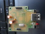
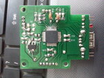
USB_DATA_LOGGER.jpg


usb_data_logger_top.jpg

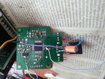
In working condition :

usb_data_logger_working.jpg


This the pcb of data logger.......

- - - Updated - - -

Please ignore the poor connections , it is just a prototype with few wrong connection on the regulator , otherwise the circuit is fine......i am able to communicate to the mcu using hyper terminal , the usb part is not working , the device is not detected.

- - - Updated - - -

Description :

Green and yellow wire are 5v and Gnd respectively . Using lm1117 3.3 V regulator for power up the mcu . Using 5V and a wire -> connected to resistor dividor to connect the 2.5V to AN8 PIN .

5pin connector is the programming connector......
3 pin connector is tx,rx gnd for communication to mcu . I have connected the tx , rx , gnd to max232 for communication to hyper terminal.......
one led is connected to RC14 for indication .....
 
Last edited:

I am using Pic24FJ64GB002. I want to use flash drive for file system access, so any way i have to work on c30 and MLA usb host library.

Is Uart working in the set baud rate? If yes then no problem about the frequency part. also usb uses a special PLL output of 48MHz to access the USB bus.

take the exact word you are getting through UART like "No media found" search file contents in your project for that word

find the function which returns the output and go to MLA help for the particular function and returning value..
 

I tried the USB data logger
C:\microchip_solutions_v2013-06-15\USB\Host - Mass Storage - Thumb Drive Data Logger\Firmware\USB Host - Mass Storage - Thumb Drive Data Logger - XC16.mcp

on an Explorer 16 board with a PIC24FJ256GB110
works OK when built with either C30 or XC16, e.g.

datalog.jpg

as you are getting output to PC terminal your config and crystal baud rate calculations must be OK

can you put an oscilloscope on the D- and D+ lines to see if the levels etc look correct
 
jit_singh_tara, why don you test your hardware with code compiled by horace1.

horace1 can you please compile the code for the given controller with your existing code and post the hex file.

we can see if anything wrong with the modified source file. also i think you have to check the UART pin configuration before doing so.

jit_singh_tara, Do you have OTG config tool from your MLA? but i think if you go through it you have to start from beginning.
 
if I try to build with device PIC24FJ64GB106 I get an error
Code:
Executing: "C:\Program Files (x86)\Microchip\MPLAB C30\bin\pic30-gcc.exe" -mcpu=24FJ64GB106 -x c -c   "usb_data_logger.c" -o".\Objects\USB Data Logger - XC16\usb_data_logger.o" -I"." -I"..\..\..\Microchip\Include" -D__DEBUG -g -Wall
usb_data_logger.c:91:10: error: #error "Device not supported.  Please add support."
 

Signals on D+ AND D- LINES ARE AS FOLLOWS :


D+ : 3.2 V DC ....
D- : 0V......

tHERE IS no pulse.........on th elines even if i give command on the hyper terminal.......
 

Try Putting the CRO pin on D+ or D- and then connect the flash drive.

horace1, for me too
Untitled.png

I have installed the MLA version and tried with XC16..
 

Yes horace ,
plz select the device i used pic24fj65gb106 and compile your code .... post hex file so that i can check .......if the problem is with my hardware or software side......!

- - - Updated - - -

I guess you selected GA106 ... PLEASE SELECT GB106......
 

No use

Code C - [expand]
1
2
3
4
5
6
7
#if defined(__PIC24FJ256GB110__) || defined(__PIC24FJ256GB210__) || defined(__PIC24FJ256DA210__)
        #define SCAN_MASK                   0x0130      // Mask for AN4, AN5, and AN8
    #elif defined(__PIC24FJ64GB004__)
        #define SCAN_MASK                   0x01C0      // Mask for AN6, AN7, and AN8
    #else
        #error "Device not supported.  Please add support."
    #endif


These are the supported devices

- - - Updated - - -

But if we delete this part of code ADC will not work. If we disable the ADC then by changing UART config, we can test the program I think thats what the Microchip support did..
 

tried the latest version of the MLA I have and built
C:\microchip\mla\v2013_12_20\apps\usb\host\msd_data_logger

for the Explorer 16 and it runs OK

howeve that does not seem to support the pic24fj64GB106 either
 

posted wrong error message
the pic24fj64gb106 gave same error message
Code:
Executing: "C:\Program Files (x86)\Microchip\MPLAB C30\bin\pic30-gcc.exe" -mcpu=24FJ64GB106 -x c -c   "usb_data_logger.c" -o".\Objects\USB Data Logger - XC16\usb_data_logger.o" -I"." -I"..\..\..\Microchip\Include" -D__DEBUG -g -Wall
usb_data_logger.c:91:10: error: #error "Device not supported.  Please add support."

however, the pic24fj64gb106 does support USB so it maay just be a question of getting the config correct
 

I am now only building the hardware, It would be better If we solve the problem soon for other controllers. tomorrow i will go through the code.

jit_singh_tara you search for the reasons for returning No media error. I think you had the one same in #27. but horace1 did you connected the drive after that?

- - - Updated - - -

Yes thats what i think too....

Untitled.png


Yeah thats what they did on your modified code.
 

PLease let me know what config setting are you using ........

:


snapshot.JPG


Should i use PIC24F_Starter_Kit_1 or something else .......plz clarify its purpose
 

the PIC24F starter kit has a PIC24FJ256GB106 and can be buit using the latest MLA
I built it using
C:\microchip\mla\v2013_12_20\apps\usb\host\msd_data_logger

with MPLABX and XC16 - the starter board programmed OK and when I plugged in the USB drive the RED LED flashed and a file LOG.CSV was created
when plugged into a PC the file was empty so I guess I am not running it correctly

you can download the starter kit user guide from
https://www.microchip.com/Developmenttools/ProductDetails.aspx?PartNO=DM240011

which has schematics of the circuit

it appears to use the internal oscillator
Code:
// CONFIG2
#pragma config POSCMD = HS              // Primary Oscillator Select (HS Oscillator Enabled)
#pragma config WDTCLK = LPRC            // WDT Clock Source Select bits (WDT uses LPRC)
#ifdef OSCIOFCN_ON
#pragma config OSCIOFCN=ON              // OSCO/CLKO/RC15 functions as port I/O (RC15)
#else
#pragma config OSCIOFNC=ON              // OSCO/CLKO/RC15 functions as port I/O (RC15)
#endif
#pragma config FCKSM = CSDCMD           // Clock Switching and Fail-Safe Clock Monitor Configuration bits (Clock switching and Fail-Safe Clock Monitor are disabled)
#pragma config FNOSC = PRIPLL           // Initial Oscillator Select (Primary Oscillator with PLL module (XTPLL,HSPLL, ECPLL))
#pragma config ALTADREF = AVREF_RA      // External 12-Bit A/D Reference Location Select bit (AVREF+/AVREF- are mapped to RA9/RA10)
#pragma config ALTCVREF = CVREF_RA      // External Comparator Reference Location Select bit (CVREF+/CVREF- are mapped to RA9/RA10)
#pragma config WDTCMX = WDTCLK          // WDT Clock Source Select bits (WDT clock source is determined by the WDTCLK Configuration bits)
#pragma config IESO = OFF               // Internal External Switchover (Disabled)
 

the PIC24F starter kit kit has no button so could not see anyway of stopping the data logger
updated code to include a counter so after 50 records were written the file was closed
when plugged into a PC the resultant LOG.CSV file contained data read from the pot

found another configuration under pic24f_starter_kit in file system.c
Code:
/** CONFIGURATION Bits **********************************************/
#pragma config JTAGEN = OFF
#pragma config GCP = OFF
#pragma config GWRP = OFF
#pragma config FWDTEN = OFF
#pragma config ICS = PGx2

#pragma config PLL_96MHZ = ON
#pragma config IESO = OFF
#pragma config FCKSM = CSDCMD
#pragma config OSCIOFNC = ON
#pragma config POSCMOD = HS
#pragma config FNOSC = PRIPLL
#pragma config PLLDIV = DIV3
#pragma config IOL1WAY = ON
again using the the Fast RC oscillator with Postscaler and PLL module (FRCPLL)
 

Status
Not open for further replies.

Similar threads

Part and Inventory Search

Welcome to EDABoard.com

Sponsor

Back
Top