Continue to Site

Welcome to EDAboard.com

Welcome to our site! EDAboard.com is an international Electronics Discussion Forum focused on EDA software, circuits, schematics, books, theory, papers, asic, pld, 8051, DSP, Network, RF, Analog Design, PCB, Service Manuals... and a whole lot more! To participate you need to register. Registration is free. Click here to register now.

[SOLVED] 16X4 Lcd displaying unreadable characters with Pic18f4550

Status
Not open for further replies.

Praveen Kumar P S

Member level 4
Joined
Aug 21, 2014
Messages
79
Helped
1
Reputation
2
Reaction score
1
Trophy points
8
Location
India
Activity points
627
Hey GUYS........
I'm new to pic programming and to this forum. I'm trying to program a pic18f4550 which receives data from virtual terminal(isis) and display it on a 16x4 lcd display....But it displays unreadable characters like α α α α

My Compiler:: CCS C Compiler 5.015
HERE is my prgm:

Code:
#include <18f4550.h> 
#fuses HSPLL,NOWDT,NOPROTECT,NOLVP,NODEBUG,USBDIV,PLL5,CPUDIV1,VREGEN,NOPBADEN 
#use delay(clock=48000000) 
#use rs232(baud=56000, xmit=PIN_C6,parity=N,rcv=PIN_C7,ERRORS,bits=8)            
#include <flex_lcd416.c> 
void main()                                        
{ 
for(;;) 
  { 
    lcd_init();                  
    lcd_setcursor_vb(1,1);    
    lcd_putc("Receving Data\n"); 
    delay_ms(1000);                                                                        
  
    if(kbhit()) 
    {    
    lcd_putc(getc());  
    output_high(PIN_A0); 
    delay_ms(500); 
    }                                
    else                                                        
    {                  
    output_low(PIN_A0); 
    delay_ms(100); 
    } 
} 
                                            
}

Here is my LCD Driver:
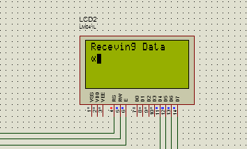
Code:
             // flex_lcd.c 

// These pins are for the Microchip PicDem2-Plus board, 
// which is what I used to test the driver.  Change these 
// pins to fit your own board. 

#define LCD_DB4   PIN_B4                                    
#define LCD_DB5   PIN_B5 
#define LCD_DB6   PIN_B6 
#define LCD_DB7   PIN_B7 
#define LCD_RS    PIN_C0 
#define LCD_RW    PIN_C1                        
#define LCD_E     PIN_C2 
                                                  
// If you only want a 6-pin interface to your LCD, then 
// connect the R/W pin on the LCD to ground, and comment 
// out the following line. 

#define USE_LCD_RW   1 

//======================================== 

#define lcd_type 2        // 0=5x7, 1=5x10, 2=2 lines 
#define lcd_line_two 0x40 // LCD RAM address for the 2nd line 


int8 const LCD_INIT_STRING[4] = 
{ 
 0x20 | (lcd_type << 2), // Func set: 4-bit, 2 lines, 5x8 dots 
 0xc,                    // Display on 
 1,                      // Clear display 
 6                       // Increment cursor 
 }; 


//------------------------------------- 
void lcd_send_nibble(int8 nibble) 
{ 
// Note:  !! converts an integer expression 
// to a boolean (1 or 0). 
 output_bit(LCD_DB4, !!(nibble & 1)); 
 output_bit(LCD_DB5, !!(nibble & 2)); 
 output_bit(LCD_DB6, !!(nibble & 4)); 
 output_bit(LCD_DB7, !!(nibble & 8)); 

 delay_cycles(1); 
 output_high(LCD_E); 
 delay_us(2); 
 output_low(LCD_E); 
} 

//----------------------------------- 
// This sub-routine is only called by lcd_read_byte(). 
// It's not a stand-alone routine.  For example, the 
// R/W signal is set high by lcd_read_byte() before 
// this routine is called. 

#ifdef USE_LCD_RW 
int8 lcd_read_nibble(void) 
{ 
int8 retval; 
// Create bit variables so that we can easily set 
// individual bits in the retval variable. 
#bit retval_0 = retval.0 
#bit retval_1 = retval.1 
#bit retval_2 = retval.2 
#bit retval_3 = retval.3 

retval = 0; 

output_high(LCD_E); 
delay_cycles(1); 

retval_0 = input(LCD_DB4); 
retval_1 = input(LCD_DB5); 
retval_2 = input(LCD_DB6); 
retval_3 = input(LCD_DB7); 

output_low(LCD_E); 

return(retval); 
} 
#endif 

//--------------------------------------- 
// Read a byte from the LCD and return it. 

#ifdef USE_LCD_RW 
int8 lcd_read_byte(void) 
{ 
int8 low; 
int8 high; 

output_high(LCD_RW); 
delay_cycles(1); 

high = lcd_read_nibble(); 

low = lcd_read_nibble(); 

return( (high<<4) | low); 
} 
#endif 

//---------------------------------------- 
// Send a byte to the LCD. 
void lcd_send_byte(int8 address, int8 n) 
{ 
output_low(LCD_RS); 

#ifdef USE_LCD_RW 
while(bit_test(lcd_read_byte(),7)) ; 
#else 
delay_us(60); 
#endif 

if(address) 
   output_high(LCD_RS); 
else 
   output_low(LCD_RS); 

 delay_cycles(1); 

#ifdef USE_LCD_RW 
output_low(LCD_RW); 
delay_cycles(1); 
#endif 

output_low(LCD_E); 

lcd_send_nibble(n >> 4); 
lcd_send_nibble(n & 0xf); 
} 

//---------------------------- 
void lcd_init(void) 
{ 
int8 i; 

output_low(LCD_RS); 

#ifdef USE_LCD_RW 
output_low(LCD_RW); 
#endif 

output_low(LCD_E); 

delay_ms(15); 

for(i=0 ;i < 3; i++) 
   { 
    lcd_send_nibble(0x03); 
    delay_ms(5); 
   } 

lcd_send_nibble(0x02); 

for(i=0; i < sizeof(LCD_INIT_STRING); i++) 
   { 
    lcd_send_byte(0, LCD_INIT_STRING[i]); 

    // If the R/W signal is not used, then 
    // the busy bit can't be polled.  One of 
    // the init commands takes longer than 
    // the hard-coded delay of 60 us, so in 
    // that case, lets just do a 5 ms delay 
    // after all four of them. 
    #ifndef USE_LCD_RW 
    delay_ms(5); 
    #endif 
   } 

} 

//---------------------------- 

void lcd_gotoxy(int8 x, int8 y) 
{ 
int8 address; 

if(y != 1) 
   address = lcd_line_two; 
else 
   address=0; 

address += x-1; 
lcd_send_byte(0, 0x80 | address); 
} 

//----------------------------- 
void lcd_putc(char c) 
{ 
 switch(c) 
   { 
    case '\f': 
      lcd_send_byte(0,1); 
      delay_ms(2); 
      break; 

    case '\n': 
       lcd_gotoxy(1,2); 
       break; 

    case '\b': 
       lcd_send_byte(0,0x10); 
       break; 

    default: 
       lcd_send_byte(1,c); 
       break; 
   } 
} 

//------------------------------ 
#ifdef USE_LCD_RW 
char lcd_getc(int8 x, int8 y) 
{ 
char value; 

lcd_gotoxy(x,y); 

// Wait until busy flag is low. 
while(bit_test(lcd_read_byte(),7)); 

output_high(LCD_RS); 
value = lcd_read_byte(); 
output_low(lcd_RS); 

return(value); 
} 
#endif 

void lcd_setcursor_vb(short visible, short blink) { 
  lcd_send_byte(0, 0xC|(visible<<1)|blink); 
}

here is the output:

7923459500_1408617758.png


plzzz help me guys..............:bang::bang::bang::bang:
 

hello,


lcd_putc write a caractere not a string..
use lcd_put_text(...
or similar function

if you have not this kind of function, write one like this

Code:
char s[21]; // table to store a string  // in Ram


void Lcd_Put_String(char * t)
{
char * p;
p=t;   // use p pointer to don't modify the  original t pointer
while(*p>0)
{
lcd_putc(*p):
p++;
}


... in main program
lcd_setcursor_vb(1,1);  // set cursor on the right place
strcyprgm2ram(s,"Receveiving Data);                             // function to transfer ROM string to RAM string
Lcd_Put_String(s);   //
 
lcd_putc("Receving Data\n")
change to
lcd_putc("Receving Data")

First of thnk u very much for that quick replay....:-D

I tried it....but still the same.....:bang::bang::bang::bang::bang:

Is their any thing wrong in the program....???:roll:

Thank u......
 

paulfjujo was right !
i didnt go through your program much yesterday, switch case you are using the function lcd_puts doesnt work. comparision neither a string nor a ascii.
 
paulfjujo was right !
i didnt go through your program much yesterday, switch case you are using the function lcd_puts doesnt work. comparision neither a string nor a ascii.

I change my lcd driver to the below one.....

Code:
    // Flex_LCD416.c 

// These pins are for my Microchip PicDem2-Plus board, 
// which I used to test this driver. 
// An external 20x4 LCD is connected to these pins. 
// Change these pins to match your own board's connections. 

#define LCD_DB4   PIN_B4 
#define LCD_DB5   PIN_B5 
#define LCD_DB6   PIN_B6 
#define LCD_DB7   PIN_B7 

#define LCD_RS    PIN_C4 
#define LCD_RW    PIN_C5 
#define LCD_E     PIN_C6 

/* 
// To prove that the driver can be used with random 
// pins, I also tested it with these pins: 
#define LCD_DB4   PIN_D4 
#define LCD_DB5   PIN_B1 
#define LCD_DB6   PIN_C5                    
#define LCD_DB7   PIN_B5 

#define LCD_RS    PIN_E2 
#define LCD_RW    PIN_B2 
#define LCD_E     PIN_D6 
*/ 

// If you want only a 6-pin interface to your LCD, then 
// connect the R/W pin on the LCD to ground, and comment 
// out the following line.  Doing so will save one PIC 
// pin, but at the cost of losing the ability to read from 
// the LCD.  It also makes the write time a little longer 
// because a static delay must be used, instead of polling 
// the LCD's busy bit.  Normally a 6-pin interface is only 
// used if you are running out of PIC pins, and you need 
// to use as few as possible for the LCD. 
#define USE_RW_PIN   1      


// These are the line addresses for most 4x20 LCDs. 
#define LCD_LINE_1_ADDRESS 0x00 
#define LCD_LINE_2_ADDRESS 0x40 
#define LCD_LINE_3_ADDRESS 0x10 
#define LCD_LINE_4_ADDRESS 0x50 

// These are the line addresses for LCD's which use 
// the Hitachi HD66712U controller chip. 
/* 
#define LCD_LINE_1_ADDRESS 0x00 
#define LCD_LINE_2_ADDRESS 0x20 
#define LCD_LINE_3_ADDRESS 0x40 
#define LCD_LINE_4_ADDRESS 0x60 
*/ 


//======================================== 

#define lcd_type 2   // 0=5x7, 1=5x10, 2=2 lines(or more) 

int8 lcd_line; 

int8 const LCD_INIT_STRING[4] = 
{ 
 0x20 | (lcd_type << 2),  // Set mode: 4-bit, 2+ lines, 5x8 dots 
 0xc,                     // Display on 
 1,                       // Clear display 
 6                        // Increment cursor 
 }; 


//------------------------------------- 
void lcd_send_nibble(int8 nibble) 
{ 
// Note:  !! converts an integer expression 
// to a boolean (1 or 0). 
 output_bit(LCD_DB4, !!(nibble & 1)); 
 output_bit(LCD_DB5, !!(nibble & 2)); 
 output_bit(LCD_DB6, !!(nibble & 4));    
 output_bit(LCD_DB7, !!(nibble & 8));    

 delay_cycles(1); 
 output_high(LCD_E); 
 delay_us(2); 
 output_low(LCD_E); 
} 

//----------------------------------- 
// This sub-routine is only called by lcd_read_byte(). 
// It's not a stand-alone routine.  For example, the 
// R/W signal is set high by lcd_read_byte() before 
// this routine is called.      

#ifdef USE_RW_PIN 
int8 lcd_read_nibble(void) 
{ 
int8 retval; 
// Create bit variables so that we can easily set 
// individual bits in the retval variable. 
#bit retval_0 = retval.0 
#bit retval_1 = retval.1 
#bit retval_2 = retval.2 
#bit retval_3 = retval.3 

retval = 0; 
    
output_high(LCD_E); 
delay_us(1); 

retval_0 = input(LCD_DB4); 
retval_1 = input(LCD_DB5); 
retval_2 = input(LCD_DB6); 
retval_3 = input(LCD_DB7); 
  
output_low(LCD_E); 
delay_us(1); 
    
return(retval);    
}    
#endif 

//--------------------------------------- 
// Read a byte from the LCD and return it. 

#ifdef USE_RW_PIN 
int8 lcd_read_byte(void) 
{ 
int8 low; 
int8 high; 

output_high(LCD_RW); 
delay_cycles(1); 

high = lcd_read_nibble(); 

low = lcd_read_nibble(); 

return( (high<<4) | low); 
} 
#endif 

//---------------------------------------- 
// Send a byte to the LCD. 
void lcd_send_byte(int8 address, int8 n) 
{ 
output_low(LCD_RS); 

#ifdef USE_RW_PIN 
while(bit_test(lcd_read_byte(),7)) ; 
#else 
delay_us(60); 
#endif 

if(address) 
   output_high(LCD_RS); 
else 
   output_low(LCD_RS); 
      
 delay_cycles(1); 

#ifdef USE_RW_PIN 
output_low(LCD_RW); 
delay_cycles(1); 
#endif 

output_low(LCD_E); 

lcd_send_nibble(n >> 4); 
lcd_send_nibble(n & 0xf); 
} 
//---------------------------- 

void lcd_init(void) 
{ 
int8 i; 

lcd_line = 1; 

output_low(LCD_RS); 

#ifdef USE_RW_PIN 
output_low(LCD_RW); 
#endif 

output_low(LCD_E); 

// Some LCDs require 15 ms minimum delay after 
// power-up.  Others require 30 ms.  I'm going 
// to set it to 35 ms, so it should work with 
// all of them. 
delay_ms(35);          

for(i=0 ;i < 3; i++) 
   { 
    lcd_send_nibble(0x03); 
    delay_ms(5); 
   } 

lcd_send_nibble(0x02); 

for(i=0; i < sizeof(LCD_INIT_STRING); i++) 
   { 
    lcd_send_byte(0, LCD_INIT_STRING[i]); 

    // If the R/W signal is not used, then 
    // the busy bit can't be polled.  One of 
    // the init commands takes longer than 
    // the hard-coded delay of 50 us, so in 
    // that case, lets just do a 5 ms delay 
    // after all four of them. 
    #ifndef USE_RW_PIN 
    delay_ms(5); 
    #endif 
   } 

} 

//---------------------------- 

void lcd_gotoxy(int8 x, int8 y) 
{ 
int8 address; 


switch(y) 
  { 
   case 1: 
     address = LCD_LINE_1_ADDRESS; 
     break; 

   case 2: 
     address = LCD_LINE_2_ADDRESS; 
     break; 

   case 3: 
     address = LCD_LINE_3_ADDRESS; 
     break; 

   case 4: 
     address = LCD_LINE_4_ADDRESS; 
     break; 

   default: 
     address = LCD_LINE_1_ADDRESS; 
     break; 
      
  } 

address += x-1; 
lcd_send_byte(0, 0x80 | address); 
} 

//----------------------------- 
void lcd_putc(char c) 
{ 
 switch(c) 
   { 
    case '\f': 
      lcd_send_byte(0,1); 
      lcd_line = 1; 
      delay_ms(2); 
      break; 
    
    case '\n': 
       lcd_gotoxy(1, ++lcd_line); 
       break; 
    
    case '\b': 
       lcd_send_byte(0,0x10); 
       break; 
    
    default: 
       lcd_send_byte(1,c); 
       break; 
   } 
} 

//------------------------------ 
#ifdef USE_RW_PIN 
char lcd_getc(int8 x, int8 y) 
{ 
char value; 

lcd_gotoxy(x,y); 

// Wait until busy flag is low. 
while(bit_test(lcd_read_byte(),7)); 

output_high(LCD_RS); 
value = lcd_read_byte(); 
output_low(LCD_RS); 

return(value); 
} 
#endif 

void lcd_setcursor_vb(short visible, short blink) { 
  lcd_send_byte(0, 0xC|(visible<<1)|blink); 
}

now lcd works perfectly....But it not works when following staments are used in the main program....

Code:
1) #use rs232(baud=56000, xmit=PIN_C6,parity=N,rcv=PIN_C7,ERRORS,bits=8) 

2) getc();

Any Ideaaa.....Guys:fight::fight::fight:
 

hello,


I didn't check all your LCD program
but if you are using RC5 bit, i suspect a probleme with PORT C, wich is concern by UART (RC7 Rx and RC6 Tx)...
try to use another bit ,not in PORT C for DB6..

to change only one bit in a port, it needs to use :
Read the PORT, then apply AND and OR function to change only one bit
without affecting other bits.

I changed my lcd from port C to Port B now my Lcd works fine......:-D
Could u please tell me how to enable serial communication with pin C6 and C7. Is Serial communication possible with other ports????:thinker:
 

Hey Guys Finally it worked ....................
I removed my lcd from port C to Port D and removed UART1 from #use 232() and it worked sucessfully..........
thanks to all guys who helped me and a special thanks to...paulfjujo....

Here is my final program::

Code:
#include <18f4550.h> 
#fuses HSPLL,NOWDT,NOPROTECT,NOLVP,NODEBUG,USBDIV,PLL5,CPUDIV1,VREGEN,NOPBADEN,BORV45,PUT
#use delay(clock=48000000)
#use rs232(baud=9600,xmit=PIN_C6,parity=N,rcv=PIN_C7,ERRORS,bits=8)
#include <flex_lcd416.c>
#include <kbd.c>

void main()
{
int p;
 lcd_init();                  
 lcd_setcursor_vb(1,1);    
 lcd_putc("Receving Data\n");                      
 delay_ms(1000); 
 for(;;)
 {  
     output_high(PIN_A0);
     p=getc();
     lcd_putc(p);
     delay_ms(100);
     printf("Data Send");
     delay_ms(100);
     } 
  }

THANK YOU............:-D:-D
 

Status
Not open for further replies.

Similar threads

Part and Inventory Search

Welcome to EDABoard.com

Sponsor

Back
Top