Continue to Site

Welcome to EDAboard.com

Welcome to our site! EDAboard.com is an international Electronics Discussion Forum focused on EDA software, circuits, schematics, books, theory, papers, asic, pld, 8051, DSP, Network, RF, Analog Design, PCB, Service Manuals... and a whole lot more! To participate you need to register. Registration is free. Click here to register now.

Queries on AC singals in Advanced Design System (ADS)

Status
Not open for further replies.

hari_preetha

Full Member level 2
Joined
Jun 30, 2014
Messages
127
Helped
0
Reputation
0
Reaction score
0
Trophy points
1,296
Activity points
2,258
Sir,
Can we check the AC signal variations using Advanced Design System 2011.10. Using Simulate > Annotate DC solution and placing from Simulation DC ADS palette of DC and producing DC voltage variations at different points of the amplifying circuit.
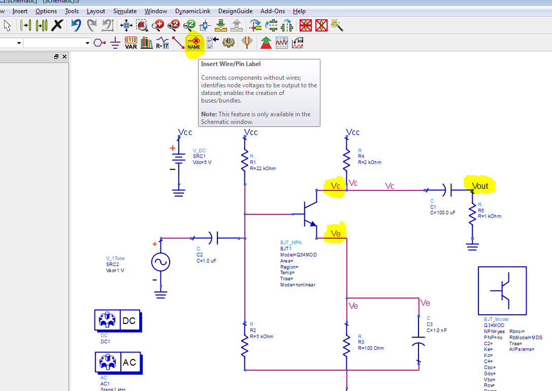
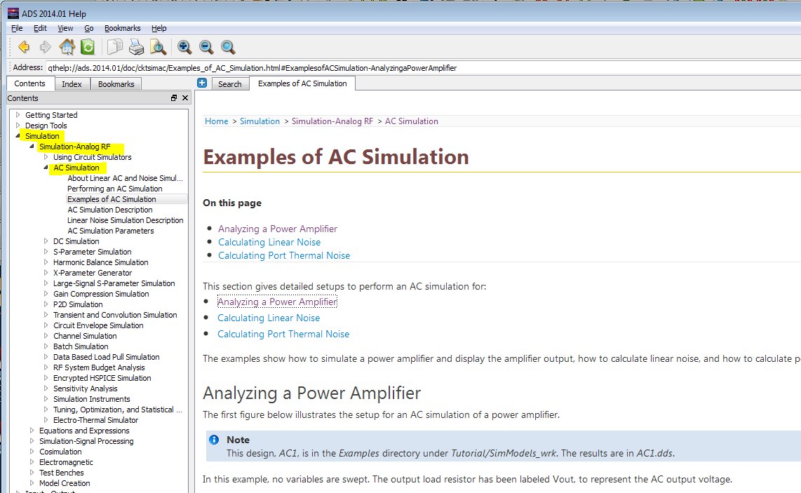
Similarly can we check AC signal amplifying in the amplifying circuit using ADS, if that option is available, can you guide me find , where it is in ADS2011.10 and how to find the AC signal variation of the amplifying circuit using ADS.
 

Not possible with annotation.
Because we define signal frequency and level i.e time varient. so if i point on a pin which level should it display as it is changing time to time.
DC annotation is possible as it is not changing wrt time.
hope you understand it
 
Sir,
Is there any other way to check the amplifying signal in amplifying circuit of different points using ADS.
 

kspalla Sir,
I am beginner to ADS, can you show me graphically, how to assign port for each node. What we have to take in ADS where we have to place, can you show me.
 

assign port for each node you want to measure
Assigned the port,where I require to measure amplifying signal, how we can get signal AC voltage at different points of circuit. What we need to use in ADS to measure AC signal.
Can someone clarify, how to measure amplifying signal in amplifier
 

Attachments

  • Amplifying_Signal_Measurment.jpg
    Amplifying_Signal_Measurment.jpg
    395.8 KB · Views: 152
Last edited:

Assigned the port,where I require to measure amplifying signal, how we can get signal AC voltage at different points of circuit. What we need to use in ADS to measure AC signal.
Can someone clarify, how to measure amplifying signal in amplifier
First, there is no AC signal source at all on your circuit consequently there isn't any signal to measure..
Why don't you read something about simulation techniques in ADS ? I'm sure there are tons of material around...
 
First, there is no AC signal source at all on your circuit consequently there isn't any signal to measure...
Sir,
My intention is to measure amplifying signal at different parts of the amplifying circuit, can I use one term(term1) at the input and other term(term2) at the as desired part in the amplifying circuit and simulate it S-parameters and can we gain at the different parts. Is it correct way of finding the amplifying signal at the different parts of the amplifying circuit.
Externally we are connecting RF input signal at the input of the amplifying circuit. Term(term1,term2....),we are using at the input and output ports of the amplifying ckt , what terms(term1,term2,term3.....) are giving to the amplifying circuit, what actually they are giving. Can you clarify it.
 

You should not use ports. Instead, use wire/pin labels. Then voltages are then available for plotting.

As always, reading the ADS online help is useful. In the help, you can get better answers than here at edaboard. The ADS online help gives instructions and helps to find examples in the ADS examples directory.


Status
Not open for further replies.

Part and Inventory Search

Welcome to EDABoard.com

Sponsor

Back
Top