Continue to Site

Welcome to EDAboard.com

Welcome to our site! EDAboard.com is an international Electronics Discussion Forum focused on EDA software, circuits, schematics, books, theory, papers, asic, pld, 8051, DSP, Network, RF, Analog Design, PCB, Service Manuals... and a whole lot more! To participate you need to register. Registration is free. Click here to register now.

Negative Directivity in HFSS.

Status
Not open for further replies.

eskim_urtigas

Newbie level 4
Joined
Dec 6, 2011
Messages
7
Helped
0
Reputation
0
Reaction score
0
Trophy points
1,281
Activity points
1,334
Hello,

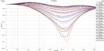
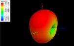
I'm simulating a very small antenna, with low radiation efficiency and gain. In some simulations (HFSS) I observed only negative directivity values.

Then I optimized the model, corrected some things such as radiation boundary box size and material, etc.
Now i observe positive and negative values. I would like to understand why I keep getting these negative directivity values.

(2 directivity plot in the attachments)

Can anyone comment on this?

Does anyone know how HFSS calculates directivity?

Thank you.
 

Attachments

  • directivity rectangular plot.JPG
    directivity rectangular plot.JPG
    217.3 KB · Views: 146
  • directivity 3d polar plot.JPG
    directivity 3d polar plot.JPG
    39.8 KB · Views: 137
Last edited:

Look at the hfss help on directivity and the topic on computing antenna parameters.
Warning: The computed values of max U and peak directivity depend on the user-determined set of aspect angles chosen for the computation of the radiated fields. If this set does not encompass the actual peak intensity of the radiated pattern, the displayed results for these three parameters will be inaccurate.
directivity = 4*pi*U/Prad where
U is the radiation intensity in watts per steradian in the direction specified.
Prad is the radiated power in watts.
My guess is that the negative has to do with direction of the beam you want vs. average beam direction.
 

I increased the size of the air box around the antenna. Now I see positive values. Still don't really understand why, but it works now. Any ideas why?
 

The directivity values given are in dB.
Look at the definition of dB:
x in dB = 10*log(x).
Any value smaller then 1 leads to negative dB value. Therefore you have a positive directivity but the representation in dB leads to negative values. Thus the directivity there is very small.
Almost every antenna has regions with very small directivity leading to negative dB values.
 
Status
Not open for further replies.

Part and Inventory Search

Welcome to EDABoard.com

Sponsor

Back
Top