Continue to Site

Welcome to EDAboard.com

Welcome to our site! EDAboard.com is an international Electronics Discussion Forum focused on EDA software, circuits, schematics, books, theory, papers, asic, pld, 8051, DSP, Network, RF, Analog Design, PCB, Service Manuals... and a whole lot more! To participate you need to register. Registration is free. Click here to register now.

[PIC] water temprature monitoring and control using PIC16F877A

Status
Not open for further replies.

KVN1477

Junior Member level 3
Joined
Nov 18, 2013
Messages
26
Helped
4
Reputation
8
Reaction score
4
Trophy points
3
Activity points
184
hi,
i have developed code for water temperature monitoring and control using PIC16F877A,LM35 & immersion heater(1500w). i don't have idea about relay circuit,Can any one tell me what should be specification of electromechanical relay to control ON/OFF of 1500W immersion heater & how to interface relay with port of PIC
 

The relay contacts need to be rated at no less than your immersion heater voltage (you haven't told us what voltage that is) and it should be rated to switch at least the heater current. Higher ratings give you a better safety margin but do not go lower. The current is Power/Voltage so divide 1500 by the voltage to get the result in Amps.

A PIC is not capable of driving a relay directly, you need an NPN transistor to work as a current amplifier. Pick a transistor capable of handling the relay coil current (again a higher rating is fine), connect a supply equal to the relay coil voltage to one end of the coil and the other end to the transistors collector pin. Wire the emitter of the transistor to ground (VSS) and connect it's base pin to the PIC pin you are using as the relay control signal through a 1K Ohm resistor. You must also add a diode (1N4001 or similar) across the relay coil wired so it DOESN'T normally conduct, in other words the cathode (banded end) to the relay supply voltage.

If you are confident with dealing with high voltages, it is easier to switch the heater with a triac, let me know.

Brian.
 
Hi,

For driving just the odd port then as Betwixt says you can use a transistor etc.

If you expect to use several outputs for heavier loads then use a Driver chip like the ULN2803A, it connects direct to the pic and relay without additional components.
See its datasheet for connections.


For relay choice its wise to over rate the devices contact power handling by 50 -100% so my choice would be to go for one capable of 3000W.
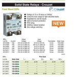
However a mechanical relay switching heavy loads creates lots of interference that often resets or upsets micros unless you are very good at circuit design, so consider using a solid state relay, a lot dearer to buy, but often cheaper in the end because of the less interference and most can be driven direct from a pic port via a resistor.
 

Attachments

  • 000017.jpg
    000017.jpg
    39.1 KB · Views: 72
better to go with SSR with Zero crossing triggering one. it has more life than electro mechanical relay and less noice.

I have faced problem while relay ON/OFF controller will get reset. u need to put proper filter and placement sufficinet place required for that.
 
Status
Not open for further replies.

Part and Inventory Search

Welcome to EDABoard.com

Sponsor

Back
Top