hassanakhtar91
Newbie level 5
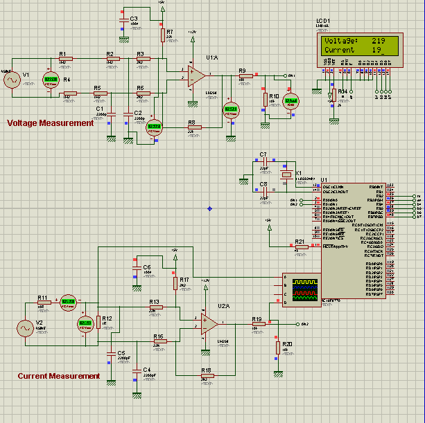
I need to measure 220 V and currents around 13 Amperes using PIC micro-controller. The circuit I have designed on Proteus using differential amplifier that converts 220 Volts to 2.5 volts (0-5 volts range) taking 40 samples of the peak voltage. The ADC of PIC is used for converting analog voltages into digital. The voltage divider divides the voltages into half so that it comes in the range of (0-5 volts) which can be read by PIC. For current measurement. 1 ohm resistor is used in parallel as a bypass and the current is measured by the voltage drop along the 1 ohm resistor using Ohm's Law. Maximum current will flow through the 1 Ohm resistor and min part of it goes towards the Op-amp.
It's showing the values of voltage and current on the input side accurately on LCD but I have some confusions regarding this circuit.
1. First of all is this circuit okay as I have some doubts about it?
2. Should I use a current transformer and voltage transformer on the input side?
3. The 1 ohm bypass resistor should be used if I use a current transformer or should I use only high power wire wound resistor only instead of CT for current measurement?
(I'm a student so I don't have much experience in this area. So kindly explain everything)
")