Continue to Site

Welcome to EDAboard.com

Welcome to our site! EDAboard.com is an international Electronics Discussion Forum focused on EDA software, circuits, schematics, books, theory, papers, asic, pld, 8051, DSP, Network, RF, Analog Design, PCB, Service Manuals... and a whole lot more! To participate you need to register. Registration is free. Click here to register now.

Query regarding Input common mode rande

Status
Not open for further replies.

rishabh_31ec

Member level 1
Joined
Sep 13, 2013
Messages
36
Helped
4
Reputation
8
Reaction score
4
Trophy points
1,288
Activity points
1,546
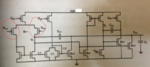
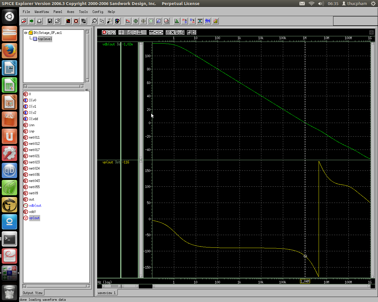
Hi, I am designing 4 stage NGCC operational amplifier in TSMC 180nm process using gm/Id methodology ( CADENCE, mixed signal design domain). I have designed upto third stage by keeping the MOSFETs in moderate inversion taking gm/Id = 7~10. Everything is fine but there is a problem regarding ICMR( Vdd = 1.5V & Vss = 0V).

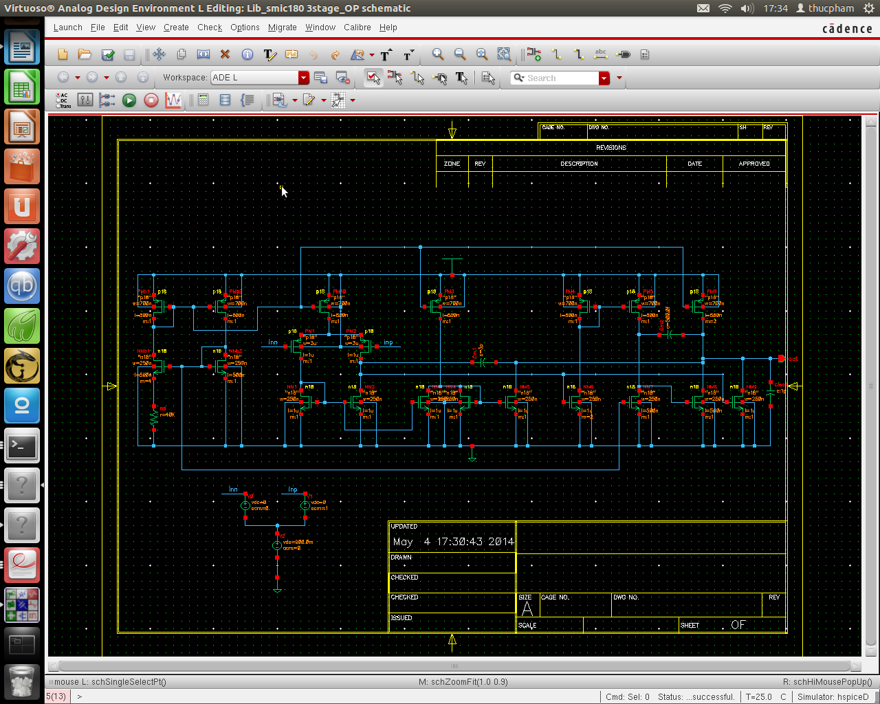
When I tied both the input together and vary the dc voltage from -0.12V to 0.43V, all the transistors remain in saturation ( only upto second stage ),but after third stage this range compress too much. (When I did DC analysis, I found that in third stage Vds drops too much below Vdsat.)

What is the exact solution? How can I improve my Input Common Mode Range.
Please reply and resolve my problem.......
 

Attachments

  • ngcc.png
    ngcc.png
    469.9 KB · Views: 73

You should connect your opamp in buffer configuration and sweep dc on noninverting input only. Each opamp has a systematic offset caused by finite gain so when You applying the same dc voltage on both inputs You amplifying it on every stage.
 
The analysis must be carried out with DC feedback or an equivalent method to keep the output operation point constant.
 

But my problem is when I tied both input and vary the dc voltage all the transistors remain in saturation for small input dc range. How can i improve this range???? It also reflects the Input Common Mode range?????
 

when I tied both input and vary the dc voltage
That's not the correct way to measure common mode parameters. You either connect a differntial input voltage and adjust it to compensate the offset voltage, or operate the amplifier in DC feedback, as suggested.
 
Thanx FVM for your valuable suggestion.
So, when I gonna make opamp as buffer and vary the DC voltage at non-inverting terminal then is it true to say that
ICMR ( Input Common Mode Range) is the range of this DC voltage (at non-inverting terminal) for which,

OUTPUT DC VOLTAGE >= INPUT DC VOLTAGE.
 

Hi rishabh_3ec
I try to design your 3 stage opamp and result look ok (gain, phase margin, ICMR) . I see there is a pole&zero doublet in your opamp. How you eliminate it ? Thanks


Hi, Tompham;
This is NGCC opamp in which zeros are cancelled out as transconductence of forward stages are made equal to that of feed-forward stages, hence only dominant pole remain within UGB. However feed-forward stages are made difficult to track forward stages at all time. That is the major limitation of this topology.
 

Hi rishabh
Thanks for reply my message. I read a good paper they shows how to remove pole and zero doublet in NGCC very simple just push 3th pole far away from 2th pole by increase gm of last stage. The disadvantage of this op amp is burn more power


Hi, Tompham
yeah, It is the fundamental requirement of any opamp that it must have only one dominant pole within UGB, and feed-forward stages are power stages so consume lots of power and hard to implement for perfect tracking of Gm.
 

Status
Not open for further replies.

Part and Inventory Search

Welcome to EDABoard.com

Sponsor

Back
Top