Continue to Site

Welcome to EDAboard.com

Welcome to our site! EDAboard.com is an international Electronics Discussion Forum focused on EDA software, circuits, schematics, books, theory, papers, asic, pld, 8051, DSP, Network, RF, Analog Design, PCB, Service Manuals... and a whole lot more! To participate you need to register. Registration is free. Click here to register now.

Bandpass filter at 2.45 Ghz

Status
Not open for further replies.

ctzof

Full Member level 3
Joined
Mar 1, 2012
Messages
157
Helped
12
Reputation
24
Reaction score
11
Trophy points
1,298
Location
Munich
Activity points
2,516
Hello,
I want to design a bandpass filter at 2.45 GHz with 100 MHz bandwidth. I don't care about a specific frequency response and a 2nd or a 3rd order filter would be good. The thing is that I want to build this filter with lumped components (LC), is that possible in such a high frequency? any suggestions? I want to use mostly 0402 and 0603 components. The main reason I want to build this filter with discrete components is because I want to have the ability to have a base structure and change later the components to make it work at 5.8 GHz (150 MHz BW) any other ideas on how I can make this? The board is a multiband software defined radio transceiver
 

I assume you need to design this filter in some kind of product.
Yes it is possible to do so, but the PCB design and PCB material will be of significant influence.
And,to simply change it to 5.8GHz lateron will be not that straight forward.

By the way, at 5.8 GHz a stripline filter will perhaps be a good choice.
One thing you will find is that just simulation and making the PCB won't do the job, you will at least need to measure and tweak the real life circuit. This means at least a spectrum analyzer with tracking generator to measure the response and a directional coupler to measure in/output matching. Better though to use a Vector Network Analyser like the VNA from MegiQ.

There is an alternative: there are a lot of monolithic filters on the market. There many of them for 2.45 an 5.8 GHz. Why not use one of them? Perhaps more expensive that a discrete filter, but easier to use. (And if you realy want to tweak that one when it comes to matching, you will need a VNA anyway, but okay that depends on the performance you need to achieve)
 
  • Like
Reactions: ctzof

    ctzof

    Points: 2
    Helpful Answer Positive Rating
Thanks for your answer. Yes the board is for a commercial product. Generally is a SDR platform working at 0-6 GHz and this filters are for the transceiver front end antennas. What I want to do is to have first a filter that works at 2.45 GHz and then change only the components while having the same filter structure to make it work at 5.8 GHz and check the functionality of the system. It´s expensive to redesign a new board and I want to have the ability to change the response of the filter just by changing some components.

I assume you mean something like that https://www.digikey.com/product-detail/en/LFB182G45SG9B740/490-4743-2-ND/1531434
That could be a very good and simple solution. The output and input impedance are 50 ohms so I don´t think I will have big problems with matching.

Any other ideas on how I can make this are welcomed.
 

Thanks for your answer. Yes the board is for a commercial product. Generally is a SDR platform working at 0-6 GHz and this filters are for the transceiver front end antennas. What I want to do is to have first a filter that works at 2.45 GHz and then change only the components while having the same filter structure to make it work at 5.8 GHz and check the functionality of the system. It´s expensive to redesign a new board and I want to have the ability to change the response of the filter just by changing some components.

I assume you mean something like that http://www.digikey.com/product-detail/en/LFB182G45SG9B740/490-4743-2-ND/1531434
That could be a very good and simple solution. The output and input impedance are 50 ohms so I don´t think I will have big problems with matching.

Any other ideas on how I can make this are welcomed.


You could look here http://www.temwell.com.tw/
they manufacture bandpass filter in many frequencies and you could shift them in large areas. Send your request and may have product ready for you.
 

Realizing a 2.4GHz filter with lumped components is pretty difficult in practice due to small component values and their tolerances.You can add layout parasitics onto this consideration.
5.8GHz filter with lumped elements ?? Forget about it. No way...
There are 2 ways.Either you will purchase fabricated standard filters or you will realize those filters on a high di-electric ( for smaller profile) and low loss tanD substrate.
Otherwise you'll have too much trouble with tolerances and layout parasitics.
 
  • Like
Reactions: ctzof

    ctzof

    Points: 2
    Helpful Answer Positive Rating
I think the the solutions with fabricated standard filters is the best I can do. It would be nice to have those helical tunable filters but they can't go higher than 2.6 GHz. Anyway is there another way to build something like a tunable bandpass filter structure so I can somehow change the center frequency and perhaps the bandwidth?
 

Sabouras again those filters can work at 3.5 GHz maximum plus they are very huge. As I wrote in my first post I want to work at 5.8 GHz. I need something like this **broken link removed**. Is there a company that can make custom bandpass filters in these dimensions so I can change the filter while at the same time keeping the same footprint? Or is there a way to design something like a micro-strip line tunable filter?
 

On that frequencies you could not made tunable filter easy. The most companies which use filter on that bands made it with cavities, or helical coils. All those filter has some tuning range but it is very small. You must consider something like a filter bank with pin diodes and change the center frequency.
One possible solution are the polezero digital tunable filter but you must ask for a custom filter because i do not think there have a filter in that frequencies. For mems and ceramic technologies which could used on those frequencies there are not ability to change the center frequency because of manufacture process.
example of saw filter http://www.golledge.com/docs/products/saws.htm?gclid=CMTNoMXzgL4CFYbMtAodw2oA8w
digital tunable filter **broken link removed**
Microstrip filter are those http://www.feko.info/applications/w...dpass-filter/mstrip_bandpass_filter_page/view
With somehow must change the line of the microstrip to change the center frequency which is the equivalent coil and the space between line for the bandwidth. I do not think is a way to change the center frequency on those filters.
 
  • Like
Reactions: ctzof

    ctzof

    Points: 2
    Helpful Answer Positive Rating
I´ve talked with my company and they told me that is possible to design those filters with microstrip lines. Is it possible to desgin them with FR4 substrate? Also is there a free tool that can help me design a those microstrip line filters like Filter solutions for example (The free version of filter solution doesn´t give a solution fro microstrip line filters).
 

I´ve talked with my company and they told me that is possible to design those filters with microstrip lines. Is it possible to desgin them with FR4 substrate?

Yes, but it will be physically large. Example calculated with Filter Solutions: for 2.45GHz and BW=100MHZ, the 5th order hairpin filter layout on FR4 will be 53mm x 15mm. Due to the bad dielectric loss of FR4, insertion loss will be around 6dB. Tolerances of FR4 permittivity will be critical, and likely cause issues.
 

Thanks. But what if I use something a third order filter and-or a Rogers substrate? Is it still going to be large and have a lot of attenuation. By the way is there a free tool like Filter solution to design those microstrip line filters? As I wrote before Free version of filter solution doesn't work with bandpass microstrip line filters.
 

Thanks. But what if I use something a third order filter and-or a Rogers substrate?

Estimated size for the 3rd order hairpin is about 3/5 the size of the 5th order. If you use Rogers substrate, the loss will be smaller but the PCB will be really expensive. The more cost effective solution will be to purchase an SMD filter (LTCC technology).

By the way is there a free tool like Filter solution to design those microstrip line filters?

No.

As I wrote before Free version of filter solution doesn't work with bandpass microstrip line filters.

I know. That's why I tried to help you, using the commercial version.
 
Last edited:
  • Like
Reactions: ctzof

    ctzof

    Points: 2
    Helpful Answer Positive Rating
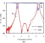
It is true that you take a repeatable frequency response pattern if you design a bandpass microstrip line filter? For example something the picture I have attached below. If these is true then is going to be a serious problem for my design. Is there a way to avoid this? 080303032146ZgnJa1.jpg
 

It is true that you take a repeatable frequency response pattern if you design a bandpass microstrip line filter?

True for basic transmission line filter designs, but you could add extra elements to reject these higher frequencies. It just takes more design work, and a bit more PCB area.
 

I used ifilter to design microstrip line filters. Is there a way to make a bandpass filter while eliminating those repeatable frequency responses at the same time?
 

Is there a way to make a bandpass filter while eliminating those repeatable frequency responses at the same time?

As I wrote above: cascade bandpass with some low pass filter that reject the spurious response.
 

Status
Not open for further replies.

Part and Inventory Search

Welcome to EDABoard.com

Sponsor

Back
Top