Welcome to our site! EDAboard.com is an international Electronics Discussion Forum focused on EDA software, circuits, schematics, books, theory, papers, asic, pld, 8051, DSP, Network, RF, Analog Design, PCB, Service Manuals... and a whole lot more! To participate you need to register. Registration is free. Click here to register now.
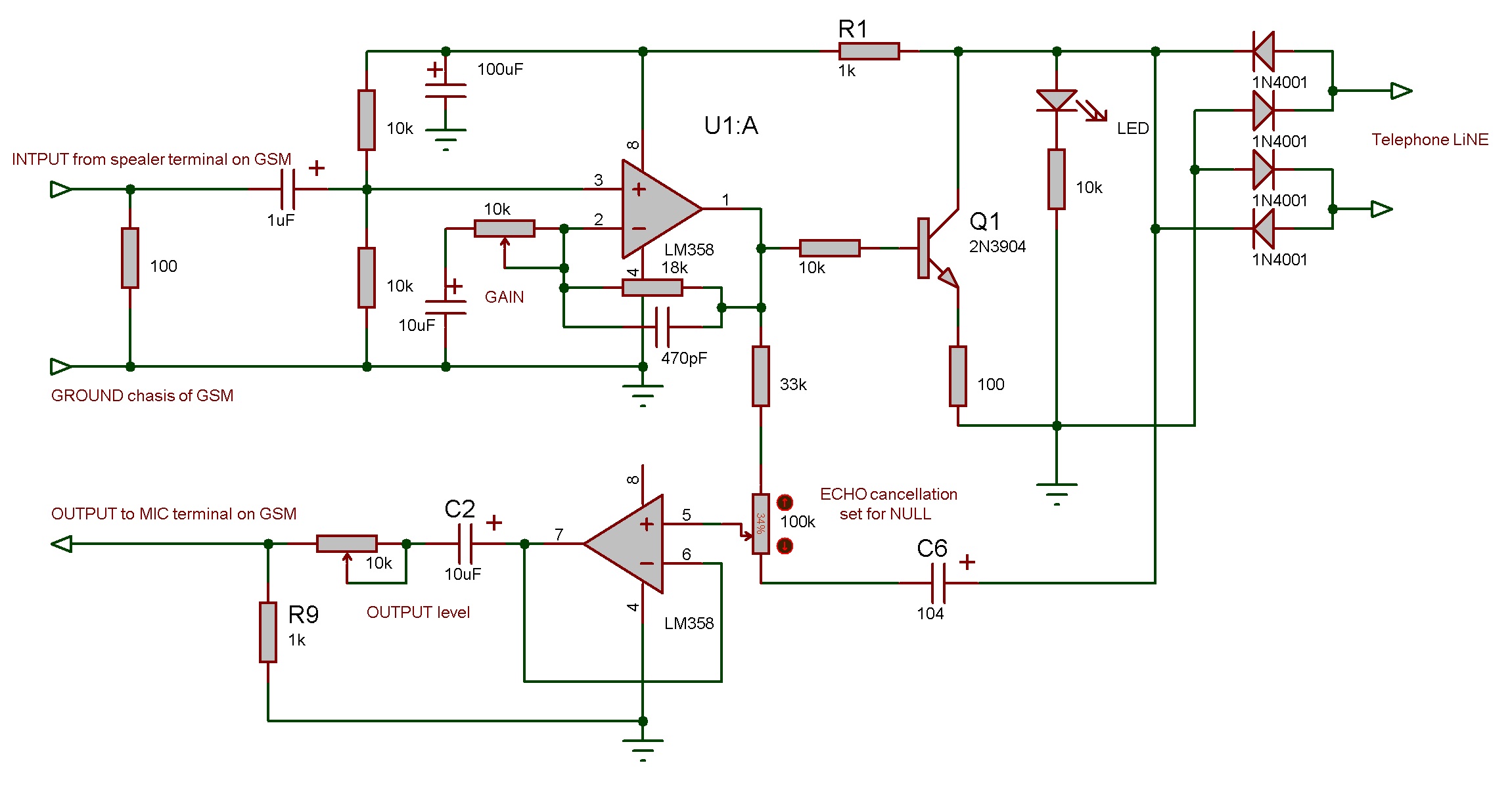
In this schematics, no external power is required. Bridge diodes can be skipped if polarity of phone line is observed manually. Use a manual switch in series with line to work as cradle.
In this schematics, no external power is required. Bridge diodes can be skipped if polarity of phone line is observed manually. Use a manual switch in series with line to work as cradle.
Are you sure schematic does not short electricity. I stuck with some short circuit position. Pin 4 get +46.6 V. Transistor base has the same voltage without connecting GND to circuit.
Please have a look.
There are two wires in in regular telephone line. It provide DC for the telephone and audio modulated on it. When you check line voltages without telephone line there you will find 48V. When phone is connected, voltages drop below 10V.
It is because There is resistance in series. Its current will not rise than 50mA even if short it. Similar is FreeTalk telephone line output. You will connect two wires to this circuit instead of telephone. The line voltage will drop to near 8V which were 48V before.
This site uses cookies to help personalise content, tailor your experience and to keep you logged in if you register.
By continuing to use this site, you are consenting to our use of cookies.