avrsanju
Junior Member level 3
hai friends,
i have a ups board using dspic 30f2010, i know that this chip have a mpwm and can be used as complimentary.
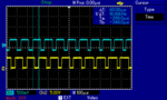
such 2 pwm, if we starting with a period of (say 100us), and we start module, we can see the wave foam both are starting together...here i want to start the second ch pwm little time later...then only i can get these type of wave foams i think..indipend ch, i measure 8khz, but in the position of TRANSFORMER (center arm of H, ican measure 16 khz,,,how can it possible?through the time shifted sloat both H arms are conducting twice?...pls clarify me...wave foarm i got her in this attachment,(1H and 2L) only.
i have a ups board using dspic 30f2010, i know that this chip have a mpwm and can be used as complimentary.
such 2 pwm, if we starting with a period of (say 100us), and we start module, we can see the wave foam both are starting together...here i want to start the second ch pwm little time later...then only i can get these type of wave foams i think..indipend ch, i measure 8khz, but in the position of TRANSFORMER (center arm of H, ican measure 16 khz,,,how can it possible?through the time shifted sloat both H arms are conducting twice?...pls clarify me...wave foarm i got her in this attachment,(1H and 2L) only.