Continue to Site

Welcome to EDAboard.com

Welcome to our site! EDAboard.com is an international Electronics Discussion Forum focused on EDA software, circuits, schematics, books, theory, papers, asic, pld, 8051, DSP, Network, RF, Analog Design, PCB, Service Manuals... and a whole lot more! To participate you need to register. Registration is free. Click here to register now.

[SOLVED] How to make an amplifier stable?

Status
Not open for further replies.
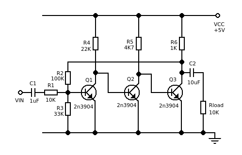
Just had another look at the graphs you showed in post 13. There is really something wrong with that circuit. I already mentioned the gain is too low and the low frequency rolloff is out by three orders of magnitude.

Now I looked at the high frequency response and noticed the gain reduces to 0dB at a frequency of about 4MHz, which is at least 10 times too low.

Can you show a screenshot from your simulator so we can see the circuit you were using?

- - - Updated - - -

as i told i'm having only 2n3904 ..tried with that but output was not found ringing.
You didn't answer any of the questions I asked.

Is 2n3904 really the only transistor in your simulator library?

i'll try one more time using simulator
Thanks. Sorry to waste your valuable time. It sounds like you've already spent almost 1/10 as much time on this as I have.

If you don't have any luck with this, I'll give you another circuit that's much less stable. You should have no problem getting that to oscillate.
 
sure..i'm on the way to my home..once i reach there.i will message you..(can you enable private message option)

- - - Updated - - -

2n3904 with 5v supply and resistors,cap are there with me to implement real circuit..before doing breadboard circuit i checked it with simulator..
 

11.jpg12.png NI's multisim simulator was used to do simulation.
 

Re: how to make amplifier stable ?

Hi, a few quick comments:

1) Why are some pulses higher than others in the second pic? :???: That's weird.

2) It looks like C1 is short circuited. What was the amplitude (positive and negative) of the input signal you used to get the output you showed?

3) Maybe you missed this in post 10:
...it oscilates with a small capacitance (e.g. 100pF or 1nF) connected across the output.
Have you tried adding a capacitor in parallel with R7 to see how it affects stability?

It is important for amplifiers to be stable with capacitive loads. The reason is the output is normally connected to something else with a cable, and cables are capacitive.
 
Re: how to make amplifier stable ?

Hi, a few quick comments:

1) Why are some pulses higher than others in the second pic? :???: That's weird.

2) It looks like C1 is short circuited. What was the amplitude (positive and negative) of the input signal you used to get the output you showed?

3) Maybe you missed this in post 10:

Have you tried adding a capacitor in parallel with R7 to see how it affects stability?

It is important for amplifiers to be stable with capacitive loads. The reason is the output is normally connected to something else with a cable, and cables are capacitive.
C1 is not short circuited. 100mv square pulse was given at the input ,i also tried using cap parallely with R7 ..no effect was shown
 

Yes, that's why I suggested that circuit in the first place. I also tried it with a supply of 5V and two different versions of 2n3904. The amount of instability varied but all of them showed ringing or oscillation, depending on the amount of capacitance connected to the output the output.

Before I tried this circuit, I tried a 2 transistor circuit that looks similar, but without the emitter follower at the output. That was very stable. Adding the emitter follower to make a 3 transistor circuit made it unstable.
 
can you please attach that spice file..so that i can have a good look at it
 

C1 is not short circuited.
OK. It's got a line drawn through the middle of it with a connection dot on each side. I didn't know you could draw something like that without it being a short circuit.

can you please attach that spice file..so that i can have a good look at it
OK, when I get home again. I use SIMetrix though, so you won't be able to run it in Multisim.
 
I will download SIMetrix..thanks a lot..i will try
 

In the meantime, maybe you'll have more luck with this circuit. It's an inverting amplifier with gain = 20dB. As a quick reality check, the quiescent voltage on the collector of Q3 should be about 2.5V. IIRC, in my simulation it was about 2.7V. Close enough. If it's too far out, you can change R3 to adjust the Q-point.

Anyway when I simulated this one, it oscillated badly and was difficult to make stable.


- - - Updated - - -

I use the free version of SIMetrix SIMPLIS. It works well and gives results almost identical to LTspice, but I find it easier to use. I've never tried Multisim.

I did use the 'student' version of Circuitmaker, until I realised it had bugs. Very annoying, the amount of time I wasted trying to figure out what I was doing wrong before I figured out Circuitmaker was giving wrong answers. Apparently there were problems with the paid-for version as well. Definitely not recommended.
 
ya..this circuit is ringing..got the oscillatory response..can you give me the circuit with 2n3904 to simulate in simetrix

- - - Updated - - -

tt.png hi godfreyl.. i simulated this design using simetrix and found the ringing output..but in real case with the same component..i'm not getting the same :(
 

Hi
The simulation file for the first circuit is attached below, you just need to unzip it.

I get output that looks like this:


I'll have a look at your new circuit now.
 

Attachments

  • stability.zip
    2.9 KB · Views: 57

    V

    Points: 2
    Helpful Answer Positive Rating
i simulated this design using simetrix and found the ringing output..but in real case with the same component..i'm not getting the same :(
I did a quick simulation when I was home, and didn't see any obvious instability.

However the input waveform you're using is a bit of a mess. You need to change a few settings on the signal generator:

1) Simetrix does stupid stuff if you set the rise time or fall time to 0. I usually set them to a valid but very low value like 1n.
2) It looks like you have pulse width set to 0 as well. To make a 100KHz square wave, you need to set period = 10uS, then either set pulse width to 5uS or set duty cycle to 50%.
3) That circuit only works well with positive input and output voltages. You can fix this for simulation by setting the voltage levels in the signal generator to e.g. +300mV and +400mV instead of +50mV and -50mV. For the actual circuit you would need to add biasing.

You may also need to change one of the simulation settings. The default value for maximum timestep chosen by Simetrix is normally too big. You can change it by clicking the "advanced" button on the simulation settings window.

I normally set max timestep to 1/1000 of the period of the input waveform. That shows plenty of detail and still simulates quite fast. So for this sort of test, I set it to 10nS.
 
  • Like
Reactions: diaz080

    V

    Points: 2
    Helpful Answer Positive Rating

    diaz080

    Points: 2
    Helpful Answer Positive Rating
Status
Not open for further replies.

Similar threads

Part and Inventory Search

Welcome to EDABoard.com

Sponsor

Back
Top