Continue to Site

Welcome to EDAboard.com

Welcome to our site! EDAboard.com is an international Electronics Discussion Forum focused on EDA software, circuits, schematics, books, theory, papers, asic, pld, 8051, DSP, Network, RF, Analog Design, PCB, Service Manuals... and a whole lot more! To participate you need to register. Registration is free. Click here to register now.

LDR as Digital POT ?

Status
Not open for further replies.

asking

Full Member level 5
Joined
Sep 21, 2010
Messages
279
Helped
6
Reputation
12
Reaction score
6
Trophy points
1,298
Activity points
3,377
Hello,

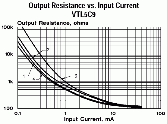
I have been searching for 50K Digital POT but it seems to be costly 5-7$ + Shipping to India. I have idea how it would be if i use PWM based LED light and use LDR as Digital Resistor ? Can i use it ? any draw backs ?

Please advice...

Thanks
 

You must not use PWM else you will amplitude modulate resistance. Use DC.
 

The LDR resistance is very non-linear with light so you would have to calibrate the PWM duty-cycle to the LDR resistance.
 

The LDR resistance is very non-linear with light so you would have to calibrate the PWM duty-cycle to the LDR resistance.
Don't want to argue if it's very non-linear or just non-linear, but there also temperature dependency and a certain memory effect. So for higher accuracy requirements, a multi-channel LDR with a compensation element for feedback is strongly suggested.
 

Ok thanks. So i can use Smooth-out (Caps) PWM signal to FED to led.

Regarding Multi-Channel LDR with Compensation ? can you explain me more ?
 

https://www.edaboard.com/threads/304251/#post1316628

Simple way to construct a LED and LDR in a house with heat shrink sleeve pack it nicely.

I used this technique to control my Fan speed Phase angle control with PWM (without zero crossing feedback)

Ref:

**broken link removed**
 

Attachments

  • LED-LDR_Optocoupler.gif
    LED-LDR_Optocoupler.gif
    4.1 KB · Views: 100
  • LED-LDR.jpg
    LED-LDR.jpg
    6.5 KB · Views: 67
  • Like
Reactions: asking

    asking

    Points: 2
    Helpful Answer Positive Rating
You cant use caps to smooth your PWM signal , you will just peak detect. Use an RC circuit to give you the PWM -> DC.
50% duty cycle = 50% of peak PWM value. Should be a linear relationship.
LDR won't be linear , but you could always create a look-up table to translate PWM / resistance required.
 

Don't want to argue if it's very non-linear or just non-linear,........
Then why did you bring it up? I realize very non-linear is a none specific term but there certainly is a large difference between the slight non-linearity of, say a digital pot's output, and the larger non-linearity of a logarithmic type response which is characteristic of an LDR.
 

Status
Not open for further replies.

Part and Inventory Search

Welcome to EDABoard.com

Sponsor

Back
Top