Continue to Site

Welcome to EDAboard.com

Welcome to our site! EDAboard.com is an international Electronics Discussion Forum focused on EDA software, circuits, schematics, books, theory, papers, asic, pld, 8051, DSP, Network, RF, Analog Design, PCB, Service Manuals... and a whole lot more! To participate you need to register. Registration is free. Click here to register now.

[SOLVED] Designing Automatic Voltage Stabilizers

Status
Not open for further replies.
Re: Designing Automatic Voltage Stabilizer

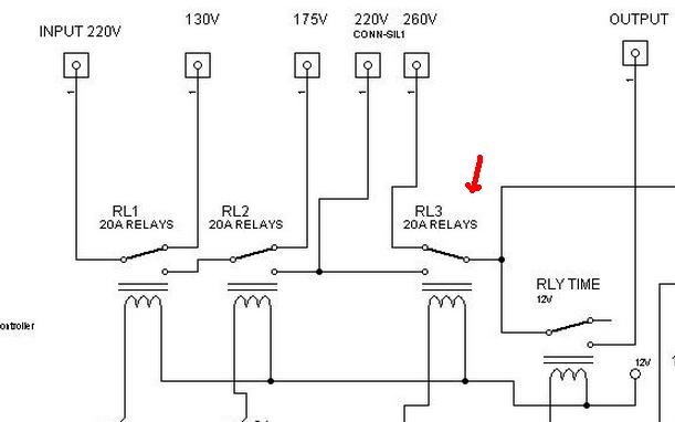
There is only 4 relays. Other is LED (rc4) and it starts blinking when out of range. If you connect a relay to this pin, it will start to do "tic tic".

I change port also . as I shown in pin configuration .,
 

Re: Designing Automatic Voltage Stabilizer

I change port also . as I shown in pin configuration .,

Post your code.

6461733700_1389697187.jpg

I think there is an error here. When input is higher than 220V. It is never connected with 260V loop.

9382476200_1389697628.jpg


Here C2 is shown for LED but in label, C4 is assigned for LED instead. In addition. "count" variable is never called. It is a compiler warning message.
 
Re: Designing Automatic Voltage Stabilizer

stabilizer is not designed for high voltage .
variable is erased in this code
here is new code and hex file

Code:
/////////////////  03124002221  lahore pakistan
   #include   <16f676.h>
   #device     adc=10
   #use        delay(clock=4000000)
   #fuses      intrc_io
   #fuses      NOWDT,PUT,NOPROTECT,BROWNOUT,NOMCLR
/////////////////////pins  lables///////////////////

   #define     relay1   pin_a1      //main   change
   #define     relay2   pin_a2      //main   change
   #define     relay3   pin_c0      //outputchange
   #define     relay4   pin_c1      //output on off
   #define     led      pin_c2      //led for indication of timer 
   #define     sw       pin_a3      //active low
   #define     low_limit      1550  // limit for low  voltage
   #define     high_limit     2450  // limit for high voltage
   #define     low_ok         2100  // value for main low  function compleate
   #define     high_ok        2440  // value for main high function compleate
   
   #define  on       output_high
   #define  off      output_low
   

////////////////////////////////////////////////////
   unsigned int32 main_v=1000;

   unsigned int8  step=1,time=0,x;
   int1           fault=0;
   unsigned int8  delay=30;

////////////////////////////////////////////////////
   void adc_read  (void);

   void relay_Set (void);

   void main_high (void);

   void main_low  (void);  
   
   void initialize(void);
   
   void  start_up (void);


/////////////////////timer1 isr//////////////////////
   #int_timer1

   void  timer1_subrutine(void)
{
   set_timer1(65536-62500);         // after 0.5S interrupt will rise

        time++;

         output_toggle(led);

            if (((time>delay)||(input(sw)==0))  &&  (fault==0)) 
   {
   
                  time=0;                          // for next round

                     on(led);

                        on(relay4);
   
                        disable_interrupts(int_timer1);

                            disable_interrupts(global);}
}

////////////////////////////////////////////////////////
   void  main()
{
   initialize();
   
   WHILE(true)
{
       start_up();
////////////////////normal loop///////////////////////////////

   do
{
   for(x=0; x<20; x++)                               //loop to perform voltage stabalization function
                                                     // if gap is larg then  only one step can not stabal voltage
{
  
      adc_read();

         if(main_v>2410)

               {step--;  if(step<1)step=1; relay_set();}     //239V

                   else if(main_v<1630)                      //200V

                     {step++; if(step>6)step=6;relay_set();}

                        else;
}
}
   while((main_v<high_limit)&&(main_v>low_limit));  // check  the limits

/////////////////////under over section///////////////////////

   fault=1;

         time=0;                                          // reset timer if it was running

         if(main_v>=high_limit)         main_high();      // call  relevent function

            else if(main_v<=low_limit)     main_low();    // call  relevent function

               disable_interrupts(int_timer1);            // reset timer and interrupt

                  disable_interrupts(global);

                           fault=0;
}

                     
}

///////////////////////////////////////////////////////////////
   void main_low  (void)
{
   enable_interrupts(int_timer1);
       enable_interrupts(global);

         off(relay4);

            off(relay3);

               off(relay2);

                off(relay1);

                  delay_ms(500);


                  while(main_v<low_ok)
{

                        time=0;

                           adc_read();

}
}
///////////////////////////////////////////////////////////////
   void main_high (void)
{
   enable_interrupts(int_timer1);

      enable_interrupts(global);

         off(relay4);

            on(relay1);

               on(relay2);

                on(relay3);

                  delay_ms(500);

                     while(main_v>= high_ok)
{

                         time=0;

                               adc_read();

}
}

///////////////////////////////////////////////////////////
   void adc_read  (void)

{
   delay_ms(20);

      main_v =read_adc();

         main_v=main_v*5000/1023;
}

 ////////////////////////////////////////////////////////////////////////////////
 void    initialize  (void)
{
   off(relay4);

      on(relay1);

         on(relay2);

            on(relay3);
/////////////input output setting////////////////////
   set_tris_a(0b11110001);

      set_tris_c(0b11111000);

         output_float(pin_a0);

            setup_adc(adc_clock_div_64);

               SETUP_ADC_PORTS(sAN0 ) ;

}
///////////////////////////////////////////////////////////////////////////////////
void     start_up    (void)
{
   delay_ms(100);

      adc_read();

         setup_timer_1(t1_internal | t1_div_by_8);

            enable_interrupts(int_timer1);

               set_timer1(65536-62500);                  //initialize for correct time

                  enable_interrupts(global);                //unmasked interrupts enable

}

///////////////////////////////////////////////////////////
  void   relay_set   (void)
  {

if(step==1)

 { on(relay1);
   on(relay2);
   on(relay3);}

   else if(step==2)
        {on(relay1);
         on(relay2);
         off(relay3);}

      else if (step==3)
           {on(relay1);
            off(relay2);
            on(relay3);}

          else if (step==4)
               {on(relay1);
                off(relay2);
                off(relay3);}

             else if (step==5)
                  {off(relay1);
                   off(relay2);
                   on(relay3);}

                else if (step==6)
                     {off(relay1);
                      off(relay2);
                      off(relay3);}

                     else;
                      }
//\/\/\/\/\/\/\/\/\/\/\/\/\/\/\/\/\/\/\/\/\/\/\/\/\/\/\/\/\/\/\/\/\/\/\/\/\/\/\
 

Attachments

  • 100v stabilizer.rar
    1.6 KB · Views: 411
Re: Designing Automatic Voltage Stabilizer

Hi Irfan


Can you explain how the relay switching works with respect to your original code? That is how the constant o/p is obtained by relay switching.
 
Re: Designing Automatic Voltage Stabilizer

Switch at pin C3 does not seem to do anything. There is no start-up timer delay of few minutes. RLY4 is not performing this functions.
 

Re: Designing Automatic Voltage Stabilizer

Dear Mr https://www.edaboard.com/members/493995/
please read post no 14 on this link https://www.edaboard.com/threads/213899/#post1203609 i have already explained this matter .


And lovely SIR https://www.edaboard.com/members/11764/
switch input is programmed to bypass timer if any user want to bypass timer.
read timer section.
Code:
/////////////////////timer1 isr//////////////////////
   #int_timer1

   void  timer1_subrutine(void)
{
   set_timer1(65536-62500);         // after 0.5S interrupt will rise

        time++;

         output_toggle(led);

            if (((time>delay)||(input(sw)==0))  &&  (fault==0)) 
   {
   
                  time=0;                          // for next round

                     on(led);

                        on(relay4);
   
                        disable_interrupts(int_timer1);

                            disable_interrupts(global);}
}

start up delay can be changed using variable named "delay".
currently it is 15 second for checking purpose.
 

Re: Designing Automatic Voltage Stabilizer

Start up delay was not working with .hex file which I compiled but now when I used your .hex file and simulated in picsimulator, it worked properly.
 
Re: Designing Automatic Voltage Stabilizer

////////////////////normal loop///////////////////////////////

do
{
for(x=0; x<20; x++) //loop to perform voltage stabalization function
// if gap is larg then only one step can not stabal voltage
{

adc_read();

if(main_v>2410)

{step--; if(step<1)step=1; relay_set();} //239V

else if(main_v<1630) //200V

{step++; if(step>6)step=6;relay_set();}

else;
}
}
while((main_v<high_limit)&&(main_v>low_limit)); // check the limits

With these values output voltage should be 200 to 295 volts.
 
start up delay can be changed using variable named "delay".
currently it is 15 second for checking purpose.
Hi,Mr irfan
i see delay value 30 for 15 second in C file.
What is value for 3 minute start up delay.
I also try to complete proteus file for your schematic and its working fine.
 

Attachments

  • IRFAN,S_STAB.rar
    15.5 KB · Views: 429

Re: Designing Automatic Voltage Stabilizer

Please help me to understand this line in your program:

Code:
 #define  sw  pin_a3  //active low

I think a3 pin in 16f676 is Mclr pin, so how it work as sw?
 
Last edited by a moderator:

I think a3 pin in 16f676 is Mclr pin, so how it work as sw?

(#fuses NOWDT,PUT,NOPROTECT,BROWNOUT,NOMCLR)
NOMCLR means,we are using this pin as input/output instead of MCLR.
 

Is this stabilizer circuit correct ? In practical circuit there will be one more tapping in the TRF and it will connect to RLY5. I made this based on this circuit. https://milan.milanovic.org/skola/mikkon/mikkon-07.htm

Depending on the voltage found out using ADC the required relay is operated so that output will be 220 or 230V.
 

Attachments

  • 16F886 stabilizer.PDF
    109.3 KB · Views: 515
Last edited:

Re: Designing Automatic Voltage Stabilizer

how i change the operating voltage range of relay under the program?
 

how i change the operating voltage range of relay under the program?
Code:
      adc_read();

         if(main_v>2410)

               {step--;  if(step<1)step=1; relay_set();}     //239V

                   else if(main_v<1630)                      //200V

                     {step++; if(step>6)step=6;relay_set();}

                        else;
}
}
   while((main_v<high_limit)&&(main_v>low_limit));  // check  the limits
2410=2.410v adc
1630=1.630v adc
If you need to change these values,you should also change high and low limits.
 
Dear pnjbtr,

Many Many Thanks.........
 
Last edited:

Re: Designing Automatic Voltage Stabilizer

stabilizer is not designed for high voltage .
variable is erased in this code
here is new code and hex file

Hi, Mr. irfan ahmad

I am new in programming. Please Help me to understand your program step by step. I don't understand various place in your program. Please help me. please.........
 
Last edited:

stabilizer circuit works like a selector switch.
which select transformer taping from transformer to maintain output voltage.
i have designed this selector switch in programming.
which reads output voltages and change selector switch position according to required output.
 

I understand the function. I just want help to understand program stepping which you write. I have another question that is this program work properly? I mean to say is it tested practically with transformer?
 

i have tested and it is working properly .
read the circuit diagram (specially relay connections ) carefully given in post #9 to understand programming.
 
Status
Not open for further replies.

Similar threads

Part and Inventory Search

Welcome to EDABoard.com

Sponsor

Back
Top