Continue to Site

Welcome to EDAboard.com

Welcome to our site! EDAboard.com is an international Electronics Discussion Forum focused on EDA software, circuits, schematics, books, theory, papers, asic, pld, 8051, DSP, Network, RF, Analog Design, PCB, Service Manuals... and a whole lot more! To participate you need to register. Registration is free. Click here to register now.

ultrasonic sensors project simulation graph

Status
Not open for further replies.

renjan

Newbie level 5
Joined
Dec 30, 2013
Messages
8
Helped
0
Reputation
0
Reaction score
0
Trophy points
1
Activity points
66
hi everyone,
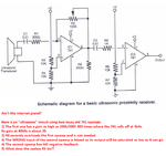
i am doing this project on ultrasnonic sensor where im using 741 and the voltage 15 to -15v need help to know how do i start? looking for a simulation graph which will help me start on this work !!

thanks

- - - Updated - - -

sorry its the ultrasonic receiver .. need to do a lit review and investigate and obtain an understanding of the receiver . plz help !
 

Re: ultrasonic sensors project help!!!!

Start by deciding what you want the receiver to do.
btw, You'll probably need a faster opamp. That means higher slew rate and higher gain bandwidth product.
 
  • Like
Reactions: renjan

    renjan

    Points: 2
    Helpful Answer Positive Rating
Re: ultrasonic sensors project help!!!!

The lousy old 741 opamp design is 46 years old. It works poorly above 9kHz.
Audio opamps work well up to 100kHz and higher. There are many of them available in The West.
 
  • Like
Reactions: renjan

    renjan

    Points: 2
    Helpful Answer Positive Rating
Re: ultrasonic sensors project help!!!!

this is an assignment given and i cant change it the specifications. hence i have to be using 741 op amp. i need a circuit design which should help me but im unsure, any help >?

- - - Updated - - -

yeah im focussing on making the reciever act as a sensor
 

Re: ultrasonic sensors project help!!!!

this is an assignment given and i cant change it the specifications.
OK, but what are the specifications? should it sound an alarm or phone the police or flush a toilet or what? Or is supposed to be measuring distance or movement or something else? Maybe a speedometer? Or an altimeter for model helicopters? Or ultrasound imaging for medical scans? Give us a clue.
 

Re: ultrasonic sensors project help!!!!

Most ultrasonic sensors are designed for 40kHz. The maximum voltage gain of a lousy old 741 opamp at 40kHz is only 25 which is not enough. Then two 741 opamps in series (each with gain of 15) must be used to get enough gain.
The low slew rate limits the output to 9kHz at 28Vp-p but if the output is reduced to about 7Vp-p then 40kHz is possible.
 

Re: ultrasonic sensors project help!!!!

this project is based upon a generic ultrasonic receiver its not based on a specific topic. i could show the specification in here

- - - Updated - - -

IMG-20131229-WA0010.jpgIMG-20131229-WA0011.jpg

- - - Updated - - -

those are the specifications .. thankyou :)
 

Re: ultrasonic sensors project help!!!!

Maybe the school assignment is a lottery?
The student who is lucky enough to find an old 741 opamp that was made on a Wednesday (instead of on a Friday or a Monday) will have a project that works at the high frequency.

I would cheat a little and use a good modern opamp that works very well at 40kHz and I would write 741 on it with a felt tip pen.
 

Re: ultrasonic sensors project help!!!!

The transducer's range may be wide enough to pick up frequencies lower than 40 kHz. As long as you are experimenting, you might try 20 kHz.

It will not deliver as strong an amplitude, but you may get enough signal that you can amplify it through a 741 op amp, at whatever gain is available (based on its gain-bandwidth product).

Here is an assortment of ultrasonic transducers, and op amp circuits.

https://www.bing.com/images/search?q=ultrasonic+receiver&FORM=HDRSC2
 

Re: ultrasonic sensors project help!!!!

The transducer's range may be wide enough to pick up frequencies lower than 40 kHz. As long as you are experimenting, you might try 20 kHz.

It will not deliver as strong an amplitude, but you may get enough signal that you can amplify it through a 741 op amp, at whatever gain is available (based on its gain-bandwidth product).
I doubt it. An ultrasonic transducer resonates at 40kHz.

Here is an assortment of ultrasonic transducers, and op amp circuits.
Hee, hee. I peeked at the first one. It is horrible with many errors:
 

Attachments

  • ultrasonic receiver.png
    ultrasonic receiver.png
    185.3 KB · Views: 149

Re: ultrasonic sensors project help!!!!

the above circuit shown is it right ? can i go ahead with using the circuit.. looks like its giving an error :/
 

Re: ultrasonic sensors project help!!!!

the above circuit shown is it right ? can i go ahead with using the circuit.. looks like its giving an error :/
The circuit in post #10 has 5 errors that are explained in RED on it.

A 6th error is that the first opamp is inverting with such a low input resistance that it overloads and reduces the level from the transducer.
 

Re: ultrasonic sensors project help!!!!

this project is based upon a generic ultrasonic receiver its not based on a specific topic.
It is for a very specific application - it's part of an ultrasonic distance measuring system.

You're not going to get very far with your project if you don't even bother to read the requirements.

The requirements seem quite clear. To summarise, you have to design, build, test, and document:
a) An amplifier for the transmitter.
b) A signal conditioning circuit for the receiver, which must include a low-pass filter.

IMHO the receiver circuit should also provide amplification and high-pass filtering, but that's not in the spec.

Anyway, you need more information before you start your design. For example:
a) What is the amplitude of the input signal to the amplifier in the transmitter circuit?
b) What is the required amplitude of the output signal from the receiver circuit?
c) What power supply voltage(s) should you use?
d) What range of distances should the UDM system be able to measure?

Fortunately, the datasheet of the transducers is easy to find on the internet, so that's no problem.

btw: The documents you showed don't say you have to use a 741 opamp.
 

Re: ultrasonic sensors project help!!!!

i need to connect the input and output of the circuit to a microcontroller to measure the distance. I think the input amplitude should be around 5v because it comes from pwm and the output amplitude should be around 5v or the output should go to voltage comparator. if it goes to voltage comparator, what would be the comparator design look like?
 

Re: ultrasonic sensors project help!!!!

suggestions on how to do the calculations to get the vzlues for the resistors ?
 

Re: ultrasonic sensors project help!!!!

suggestions on how to do the calculations to get the values for the resistors ?
The datasheet for the transducer will show a recommended value for its load which is probably high enough that an inverting opamp with a low input impedance cannot be used. So the first opamp will be non-inverting and its input resistor to ground (or to a bias voltage) will be what the transducer requires.
The feedback resistor and resistor to ground for the opamp must have values high enough so that the opamp can drive them and the datasheet for the opamp will show it.

Of course you must select an opamp that works well at the frequency you have, some opamps do not. The datasheet will show if it has enough gain at your frequency or if two opamps must share the gain required.
 

Status
Not open for further replies.

Part and Inventory Search

Welcome to EDABoard.com

Sponsor

Back
Top