Continue to Site

Welcome to EDAboard.com

Welcome to our site! EDAboard.com is an international Electronics Discussion Forum focused on EDA software, circuits, schematics, books, theory, papers, asic, pld, 8051, DSP, Network, RF, Analog Design, PCB, Service Manuals... and a whole lot more! To participate you need to register. Registration is free. Click here to register now.

8051 interfacing with rf module

Status
Not open for further replies.

go ahead

Junior Member level 1
Joined
Aug 30, 2012
Messages
15
Helped
0
Reputation
0
Reaction score
0
Trophy points
1,281
Activity points
1,421
hiii everyone..
i am trying to send 8 bit data through rf module(433 mhz)
but first i have to convert 8 bit data convert into 4 bit using 8051(AT89S52) through embedded c
i want the same data in receiver side as i send from transmitter side.
can somebody help me for the algorithm of this.


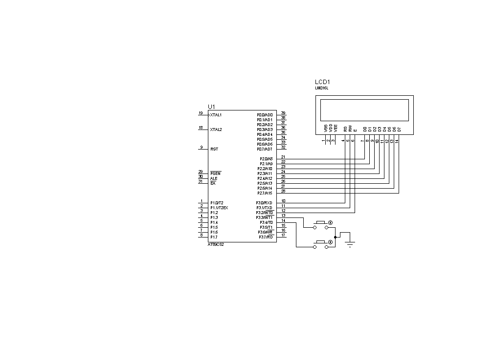
AT89S52 ---> HT12E---> rf TX(433 MHZ) ................. rf RX---->HT12D---->AT89S52---->LCD


plz help
 
Last edited:

HT12E is encoder, can't work as decoder.

You have to map 8-bit data to an unique sequence of 4-bit codes
 
HT12E is encoder, can't work as decoder.

You have to map 8-bit data to an unique sequence of 4-bit codes

yeah, its typed wrong by me sorry..

can i get any type of code in embedded c which convert 8 bit to 4 bit & again decode it from 4 bit to 8 bit ..

actually i m counting simple event like how much times switch is pressed on TX side and on RX side i want to display this values on lcd ...

TX sends the value of counter when another switch is pressed which is on TX side and at same time RX lcd shows the value of counter ..
 
Last edited:

  • Like
Reactions: go ahead

    V

    Points: 2
    Helpful Answer Positive Rating

    go ahead

    Points: 2
    Helpful Answer Positive Rating
thanx a very lot ...

can it done by 8051 too ??

on the given sites they have used PIC,AVR...

i have to do with AT89S52, RF Module and lcd
 

yes concept remains same for each controller but you have to configure the same things as there are. like UART and others.
 
i m new bee in programming ...

can u tell me the program of 2 X nibbles ..

and in both(TX & RX) can we require any baud rate ??
 

u have to divide 1 byte in two part that is in two nibble.
10101010 byte
1010 1010 2 nibbles

likewise you have to send one nibble at a time to encoder.
 

Code C - [expand]
1
2
3
4
5
6
7
8
9
10
11
12
13
14
unsigned char myData = 0xEF;
 
void main(){
 
    while(1){
 
        //RB0-RB3 connected to D0-D4 of HT12E
 
        PORTB = PORTB | (myData & 0x0F); //sending low nibble
        PORTB = PORTB | ((myData >> 4) & 0x0F); //sending high nibble
 
    }
 
}

 
- There must be a delay between nibbles
- How do you detect the start of transmision (low nibble)?
 

Yes, low nibble is sent first and at decoder it is received and appears at D0-D3 Data out pins which will be connected to receiver micro PORTB. PORTB is read like below.


Code C - [expand]
1
2
3
4
5
6
7
8
9
10
algo...
 
if read counter == 0
 
lownib = PORTB;
inc read counter
if read counter == 1
highnib = PORTB
read counter = 0
byte = highnib << 4 | lownib

 
this code will work on the TX side...
on RX side what algo is required ??

- - - Updated - - -

- There must be a delay between nibbles
- How do you detect the start of transmision (low nibble)?
in TX side i had an extra switch,which is connected to TX controller .when this switch is pressed then it will send the data .
for differentiating upper and lower nibbles i think 10 ms gap is enough.
 

That is for RX side. Tx side code was given in post #12. As FvM said add delay between sending nibbles. At receiver side data appears at D0-D3 lines only if address is valid. You can monitor VT pin using external interrupt pin and read data @ PORTx whenever there is an interrupt. ISR code has to be written which is more efficient. Mention Compiler used. If it is allowed to use software encoding/decoding then you can use manchester encoding/decoding. This will eliminate HT12x. You only need 2 micros and RF modules.


Edit: Again use external interrupt at Tx side for button. On interrupt data is sent. Use 8 pin DIP switches with both pullup and pulldown resistor pairs for the HT12x address lines. You can have 255 different addresses.
 
Last edited:
Yes, low nibble is sent first and at decoder it is received and appears at D0-D3 Data out pins which will be connected to receiver micro PORTB. PORTB is read like below.


Code C - [expand]
1
2
3
4
5
6
7
8
9
10
algo...
 
if read counter == 0
 
lownib = PORTB;
inc read counter
if read counter == 1
highnib = PORTB
read counter = 0
byte = highnib << 4 | lownib


finally i got it...
i needed one more help..
when count some event like how much time switch is pressed, then the value of counter have to be shown on lcd. then we pass it with adding +48. but still it give the garbage value..


here is my code and bit map if connections


Code C - [expand]
1
2
3
4
5
6
7
8
9
10
11
12
13
14
15
16
17
18
19
20
21
22
23
24
25
26
27
#include<reg51.h>
#include<delay1.h>
#include<lcd.h>
 
sbit sensor=P3^3; // this switch is used to increment the counter
sbit switch1=P3^4;// this switch is used to display the value of counter 
 
char a;
void main()
{
    //a=0;
    lcd_cmd(0x34);
    lcd_cmd(0x0e);
    lcd_data_string("welcome");
    while(1)
    {
        if(sensor==0)
        {
            a++;
        }
        if(switch1==0)
        {
            lcd_cmd(0x01);
            lcd_cmd(0x80);
            lcd_data(a+48);
        
        }


- - - Updated - - -

That is for RX side. Tx side code was given in post #12. As FvM said add delay between sending nibbles. At receiver side data appears at D0-D3 lines only if address is valid. You can monitor VT pin using external interrupt pin and read data @ PORTx whenever there is an interrupt. ISR code has to be written which is more efficient. Mention Compiler used. If it is allowed to use software encoding/decoding then you can use manchester coding/decoding. This will eliminate HT12x. You only need 2 micros and RF modules.


Edit: Again use external interrupt at Tx side for button. On interrupt data is sent. Use 8 pin DIP switches with both pullup and pulldown resistor pairs for the HT12x address lines. You can have 255 different addresses.

if i can get Manchester code examples for this task then i will surly remove HT12D/E
and thanx for telling me about pull up and pull down resistor for address pins..
 
Last edited by a moderator:

When switch is pressed, start timer and when switch is released stop timer. Use additional counter to store count of timer interrupts. When timer is stopped consider the value of counter and also the time remaining in the timer reload registers. Calculate time. Convert to character. External interrupt cannot be used for this purpose as it detects either leading edge or trailing edge but not both.


Code C - [expand]
1
2
3
4
5
6
7
On interrupt   //VT pin to ext int
if(nibcnt==0)
byte = (PORTB & 0x0F) << 4  //RB0-RB3 is connected to D0-D3 of HT12D
else if nibcnt == 1
byte = byte | (PORTB & 0x0F);
nibcnt++
if (nibcnt == 2)nibcnt = 0

 
Last edited:

if i can get Manchester code examples for this task then i will surly remove HT12D/E ....

Another option is to replace the ASK TX/RX pair and HT12E/D devices with transceivers which provide built-in encoding/decoding schemes, such as the Nordic Semi nRF24L01+.

A pair of transceiver nRF24L01+ based modules can be purchased for close to the same price as an ASK 433MHz TX/RX pair, as low as $2.35 shipping included.

eBay Search - nRF24L01+ 2pcs

An additional benefit is a data throughput of several magnitudes greater than achievable using ASK modules with either hardware or software encoding along with bidirectional data transmission.


There are also several C source libraries for the devices available for many microcontroller families.

nRF24L01+ Single Chip 2.4GHz Transceiver Datasheet

Atmel - 24L01 Software Driver for C51 Microcontrollers

Atmel - 24L01 Software Driver Source Code


BigDog
 

Status
Not open for further replies.

Similar threads

Part and Inventory Search

Welcome to EDABoard.com

Sponsor

Back
Top