Continue to Site

Welcome to EDAboard.com

Welcome to our site! EDAboard.com is an international Electronics Discussion Forum focused on EDA software, circuits, schematics, books, theory, papers, asic, pld, 8051, DSP, Network, RF, Analog Design, PCB, Service Manuals... and a whole lot more! To participate you need to register. Registration is free. Click here to register now.

Can we use H-bridge in general PWM inverter?

Status
Not open for further replies.
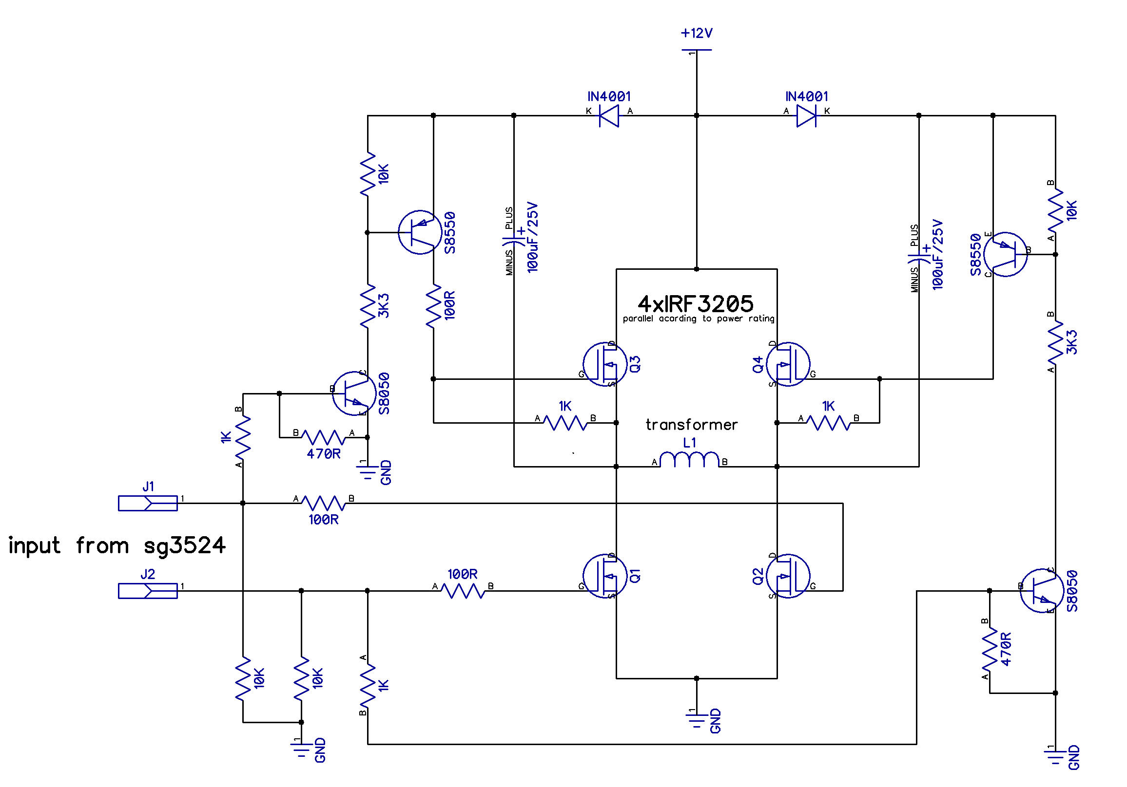
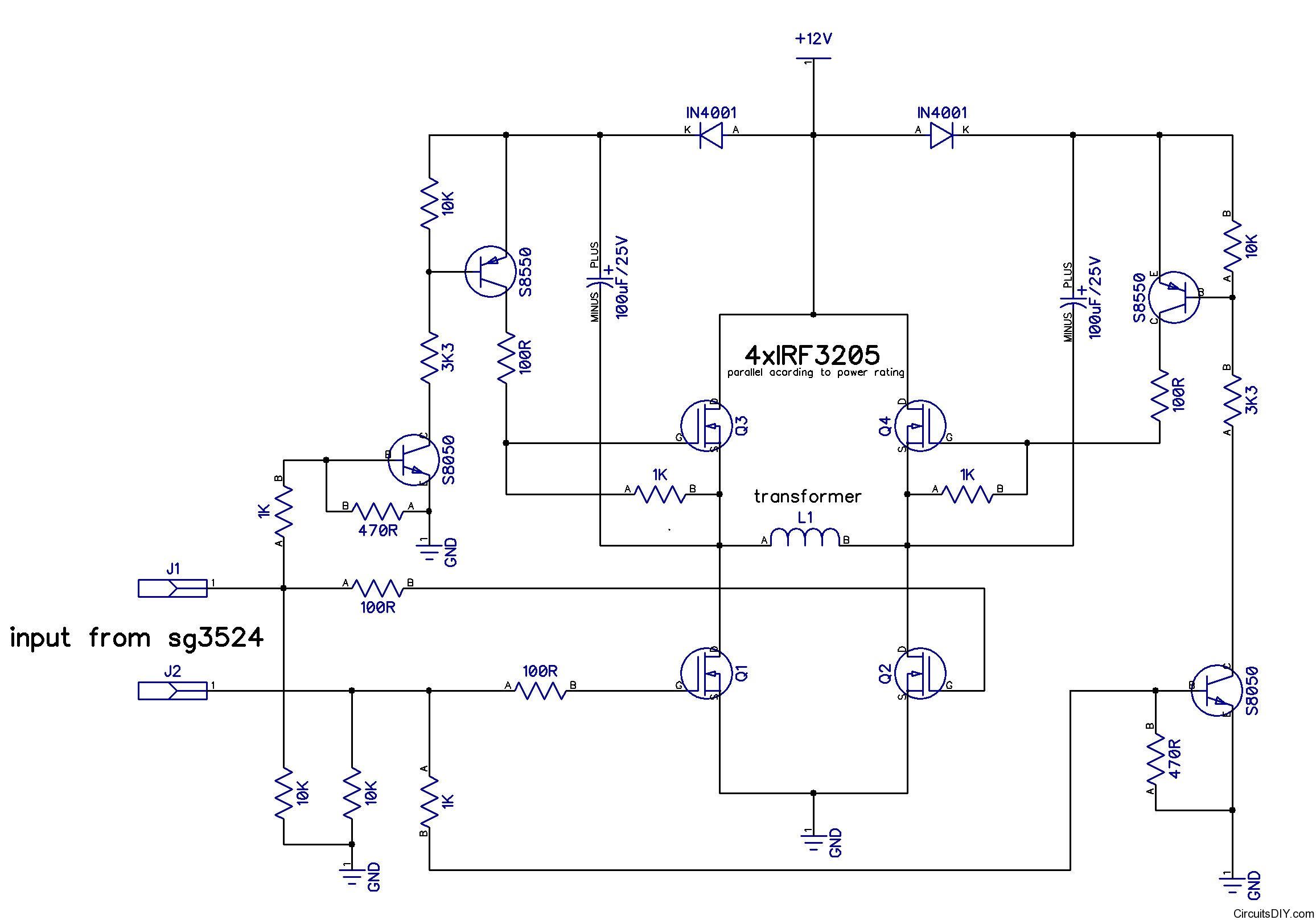
You can't connect it like that and it has been discussed as well. You would need a high-lo side driver - a floating gate driver for the high side. I would suggest you grab 2 hi-lo side drivers like IR211x/IR218x/L638x/NCP5181, etc. I think that would be the easiest way, although not the cheapest. However, that would also be the safest.

If you can not get hold of such drivers (you should quite easily be able to get IR2110 at least), you can design one using discrete components - transistor,diode,capacitor, optocoupler, etc. pnjbtr has suggested one way.

Hope this helps.
Tahmid.

What do you think of the idea that ALERTLINKS gave?
I mean https://obrazki.elektroda.pl/70_1315081864.jpg . This seems to be the easiest way for me.
 

Dear Arup,,
What you have indicated is very possible and works well except for small changes that are essential.The drive can be taken for lower Z44 in the H bridge but the high side pair willl need complete isolation and floating in phase pulses .of the same duration for which the lower mosfets are ON.
I have used a T15 toroid with bifilar dual outputs and driven by the output from pin 11 and 14 of the 3524.

The input is driven with pin 11 to ground the other terminal of the pulse tx.The sec1 is connected between Vgs of mosfet M1 and the secongd wdg. between Vgs of mosfet M3 .
Similarly , Pin 14 output drives the other T15 pulse tx. with secondary between M2 and M4.
The 230VAC was measured without any troubleshooting for faulty operation.
 
  • Like
Reactions: arupbsk

    arupbsk

    Points: 2
    Helpful Answer Positive Rating
As I said in earlier post, I'll be using a charge pump for boosting voltage.
 

Then it should work okay. It would be better if you pulled the MOSFET gates low with an NPN transistor. This would discharge the gate more quickly. However, at 50Hz, provided you have sufficient deadtime, this should be okay.

Hope this helps.
Tahmid.
 

Then it should work okay. It would be better if you pulled the MOSFET gates low with an NPN transistor. This would discharge the gate more quickly. However, at 50Hz, provided you have sufficient deadtime, this should be okay.

Hope this helps.
Tahmid.

Do you mean by one set of mosfet should instantly turn off while others are on by a transistor to prevent burn.
I remember you had once burnt a few MOSFETs in your mega32 based UPS design then you used this rule. Am I right?
 
I meant that when the high side MOSFETs are turning off in the circuit, their gate capacitance is slowly being discharged through that 1k resistor. Instead, it would be better if you pulled the gates low so that they instantly turn off.
 
  • Like
Reactions: arupbsk

    arupbsk

    Points: 2
    Helpful Answer Positive Rating
As sg3524 or sg3525(whitch have dead time setting through a resistor) is going to be used for 50Hz so there is no problem. If it is going is used at high frequency then there is an issue. It is an optimised schematic for particular reqirement.
 
Last edited:
  • Like
Reactions: arupbsk

    arupbsk

    Points: 2
    Helpful Answer Positive Rating
Thumbs up for all those who helped me. Mostly, thanks a lot alertlinks. I'll be making a custom PCB with your design for my UPS and update my success/problems in this thread in 5-10 days.
Again Thanks all of you for helping me.
 

UPDATED
Now no seperate 24v supply is needed. implemented in schematic.
Thanks again ALERTLINKS for this nice update. By the way, did you simulated the design? I mean will it have the initial energy to turn on high section MOSFEts at first PWM pulse from SG 3524?
As of my previous design, the power control (by relay and switch) was only to there +ve supply to SG3524 section. Can same be used? or do I also need to separate the IN4001+IN4001 from +12V by relay?

Waiting for your valuable reply.
 

It provides floating (high side) gate driver as mentioned in post #2
If you study how (high side) gate driver ics work, you will find similar circuit as refered in post #4
In post #12 a similar schematics is posted.
In post #19 i posted h-bridge diagramme using this technique from another thread. So it works for sure.
At first pulse when lower Fets are turned on, common point voltage reaches to zero. Hence 100uF capacitor is charged through IN4001 diode when upper FET is driven, capacitor supplies necessary voltage. FET is turned on., common point is raised towards 12V. As capacitor is charged so its voltage adds up to battery 12V making near 24v(charge pump action).
This is a standard configuration.The whole circuit remains in contact with battery. When there is positive going pulses at input it will start working. There is a shut down pin on pwm ic which can also be used to control. Normalay it is pulled up by a resistor When it is drawn low through the relay, ups starts operating.In this pwm ic also is permanently connected to 12v.
 
Last edited:

Again thanks.
Should I continue with this design? Or, I should remove the IN4148 diodes from the output of SG3524 and connect IC directly to your circuit.
**broken link removed**
 

rs25 and rs26 needs to be of low value ie around 1K. Diodes does not matter, can be connected directly. Similarly 7808 can also be skipped it drops 2-3 volts. When battery is drained, its ouput is low . IC has intenal 5V regulator and gates can withstand upto 20 volts.It is better if you replace es27 with a In4001 diode which is used on 12v input and the 10uF capacitor before 7808 behaves very naugty in this aplication. It holds up charge for few milliseconds and so ic still giving output when relay is shifted to mains. It can be replaced with 220ohm 1 watt resistor. No filter capacitor is needed and circuit stops oscilating immediately. You have to carefully set values Rt and Ct to set frequency to 50 Hz though. personall i prefer sg3525. It has enhanced features which include directly drirectly drive mosfets, programable deadtime setting, auto shutoff when supply is lowered than 7.5v.It is made to be used with FETs.
 
  • Like
Reactions: arupbsk

    arupbsk

    Points: 2
    Helpful Answer Positive Rating
Thanks.
When I tried with my design on a 2mosfet based pushpull topology power section and a 12-0-12 @ 1amp transformer, I could see the output frequency was controlled correctly, and PWM was also correct. (by two potentiometers). But at 50Hz and PWM about 70% (as seen by oscilloscope), I could see the transformer was generating much heat and consuming about 1Amp current at no load connected. Can you guess what was problem? This oscillator board, or the Power board, or the transformer?
I was taking output of 18V (controlled by PWM) from the 12,12 points of transformer's primary section and in secondary there was connected another small 220->12V transformer whose output was controlling the PWM by the oscillator board.
Power board: **broken link removed**
 

For 12+12v transformer to work at 18v, set duty cycle not more than 50%(step sine wave) or check it with 12v supply. Also check with load according to power rating of transformer.
 
  • Like
Reactions: arupbsk

    arupbsk

    Points: 2
    Helpful Answer Positive Rating
66_1315597624.jpg

For 24v, this circuit can be used.
 
I believe Arun completed this project successully.I found a page where he describes it.

https://circuitsdiy.com/h-bridge-inverter-power-stage-with-passives/

While drawing the schematic, a resistor was omitted it was not noticed hen and it does nothing spcial in the circuit. Here is corrected drawing. It is a 100 ohm resister on the right side between gate of upper right FET and transistor collector.


PCB was something like this,
7745274800_1380649284.png
 
Status
Not open for further replies.

Part and Inventory Search

Welcome to EDABoard.com

Sponsor

Back
Top