pradeep.g.belchada
Full Member level 6
- Joined
- Sep 29, 2006
- Messages
- 341
- Helped
- 85
- Reputation
- 170
- Reaction score
- 85
- Trophy points
- 1,308
- Location
- MUMBAI INDIA
- Activity points
- 2,671
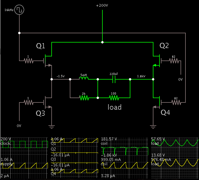
their is no cuurent limiting in your circuit the schematic i found in other thread