Continue to Site

Welcome to EDAboard.com

Welcome to our site! EDAboard.com is an international Electronics Discussion Forum focused on EDA software, circuits, schematics, books, theory, papers, asic, pld, 8051, DSP, Network, RF, Analog Design, PCB, Service Manuals... and a whole lot more! To participate you need to register. Registration is free. Click here to register now.

HELP - BUBBA Oscillator

Status
Not open for further replies.

Farrukh12

Newbie level 4
Joined
Apr 3, 2013
Messages
5
Helped
0
Reputation
0
Reaction score
0
Trophy points
1,281
Activity points
1,325
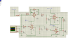
I am try to generate a 50-60 Hz sine wave using the bubba oacillator. I have my in proteus but i dont get the desired result. I have increased my gain but still no response. My schematic is:

2013-04-06_1422.png
 

All four RC time constants should be the same, so there's a couple of problems in your circuit.

Firstly, the R3C3 time constant is more than 250 times smaller than the R1C1 and R2C2 time constants. Set R3 = R1 and C3 = C1 to fix that.

Secondly, there is a problem with R4, C4 and R5. The time constant there is determined by C4 and the parallel combination of R4 and R5. There's two ways to make this the same as the other time constants:
  • Normal way: Set R4 = R1 and C4 = C1. Then set R5 >> R4 so it doesn't affect the time constant much.
  • Better way: Set C4 = C1 and choose R4 and R5 so that the parallel combination = R1. Then you need to increase the gain of the inverting stage.

Also, the non-inverting input of the top left opamp should be connected to half the supply voltage.

And finally; you may have to set an initial condition or inject a short pulse to get the oscillation started.
 
Thank You very much it worked, but in real life when i make the circuit will i still have to give it a pulse to get the oscillation started.
 
Last edited:

in real life when i make the circuit will i still have to give it a pulse to get the oscillation started.
No. Switching on the power supply will start the oscillation.
 

Dear godfreyl,

Please find attachment I made bubba oscillator circuit on proteus but it is not working,I was made changes you define but it could not worked.
 

Attachments

  • B-OSC.PNG
    B-OSC.PNG
    57.5 KB · Views: 124

R5 is loading down R4, C4 so that it does not begin oscillating. Add another opamp to buffer R4, C4 and drive the output.
 
There's no local negative feedback around U3. Connect output to inverting input, same as U2 and U4.
 
There is another error in the last circuit: The gain (inverting) must compensate the damping of each RC section at phi=45 deg.
Thus, the gain must be chosen slightly larger than "-4".
 
Dear LvW,

Please can you clear me this concept of compensation of RC section at phi=45 deg?
I shall thankful to you.
 

@Imran,An oscillator needs a total loop phase of -360 deg. The inverting amplifier contributes -180 deg. You have 4 identical RC sections which must contribute the remaining -180 deg. Thus, for each section -180/4=-45 deg. At that point, the damping of each section is 1/sqrt(2) - in total for all 4 sections: 1/4. Therefore, the gain must be (slightly larger than) -4.
 
Last edited:
I am trying to simulate the bubba oscillator on Proteus. Anyone could tell me if this is the proper working?

bubba.jpg
 

I am trying to simulate the bubba oscillator on Proteus. Anyone could tell me if this is the proper working?

Hi Denis
What is your problem ? out put of a bubba oscillator is a pretty precise sine wave . so what do you think according to this now ?

Best Wishes
Goldsmith
 
Dear Denis,

Please use circuit on post#5 ,this circuit works well and generate precise sinewave but only one wire is missed inverting input of U3 connect to its output.
Connect this wire and after simulate in proteus press button you will see output.
 
Hi Denis
What is your problem ? out put of a bubba oscillator is a pretty precise sine wave . so what do you think according to this now ?

Best Wishes
Goldsmith

Hi Goldsmith

I just wanted to make sure that the circuit was ok. It's the first time I try to do this and I had no information about the supplies...

Thanks!

- - - Updated - - -

Thank you very much!
 

Hi Denis,
The value of your R1 is WAY TOO LOW! It is an extremely heavy load on R6 and C5 and it tries to make U1A clip the waveform into a square-wave.
Try the circuit with 560k or 470k for R1.
 
I am trying to do a dc/ac inverter, but it's not clear to me why and how the voltage increases to 170 V on the output. I have found some researches but they don't explain what happens exactly in each part of the circuit.
I would like to know why we need sine and triangle waves, what the pwm and h-bridge do and etc...

Thanks

dc ac.png
 

The opamps are actually used as comparators to compare the input sine-wave with a triangle-wave. The output is Pulse-Width-Modulation (PWM) to the Mosfets that simply turn fully on and fully off with the on and off times varied by the sine-wave.

The output is 170V because it has a 170V supply and it switches fully on and fully off.
 

I am trying to do a dc/ac inverter, but it's not clear to me why and how the voltage increases to 170 V on the output. I have found some researches but they don't explain what happens exactly in each part of the circuit.
I would like to know why we need sine and triangle waves, what the pwm and h-bridge do and etc...
Hi Denis
It is simple ! if you use a comparator and compare a triangle wave and a sine wave together which frequency of triangle wave is almost 10 time larger than sine wave then you'll have a good SPWM signal .
it is a square wave which it's duty cycle is going to be changed so we can easily amplify it by a saturated amplifier like H bridge which is in class D arrangement . then the out put will be about the supply rail .
e.g SPWM with amplitude of 170 volts in your case . after adding an LPF then HF component will be removed from the spectrum of SPWM signal and what can be stay is just lowest frequency around the spectrum which is your sine wave which it's amplitude has been amplified by 170 volts . that's all .
Any question ?

Best Wishes
Goldsmith
 

Status
Not open for further replies.

Similar threads

Part and Inventory Search

Welcome to EDABoard.com

Sponsor

Back
Top