Continue to Site

Welcome to EDAboard.com

Welcome to our site! EDAboard.com is an international Electronics Discussion Forum focused on EDA software, circuits, schematics, books, theory, papers, asic, pld, 8051, DSP, Network, RF, Analog Design, PCB, Service Manuals... and a whole lot more! To participate you need to register. Registration is free. Click here to register now.

DS1307, How to set hours register

Status
Not open for further replies.
Joined
Dec 4, 2012
Messages
4,280
Helped
822
Reputation
1,654
Reaction score
791
Trophy points
1,393
Location
Bangalore, India
Activity points
0
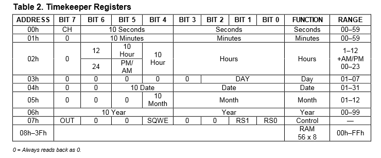
To set hour register of DS1307 I need to write these values

12 AM 0x40
01 AM 0x41
02 AM 0x42
03 AM 0x43
04 AM 0x44
05 AM 0x45
06 AM 0x46
07 AM 0x47
08 AM 0x48
09 AM 0x49
10 AM 0x50
11 AM 0x51
12 PM 0x72
01 PM 0x61
02 PM 0x62
03 PM 0x63
04 PM 0x64
05 PM 0x65
06 PM 0x66
07 PM 0x67
08 PM 0x68
09 PM 0x69
10 PM 0x70
11 PM 0x71


My hr, min, sec variables hold values

0, 1, 2, 3, 4, 5, 6 7, 8, 9, 10, 11, 12, and I have to use Dec2BCD and convert

40, 41, 42, 43,...52 and 61, 62,...71 to BCD and write it to hours register.

Is there any formula to convert 1, 2, 3, 4, 5,...12 to 40, 41, 42,....52 and 61, 62, 63,...71

I need this for the Set_Time() function in my code.
 
Last edited:

I know that. My question is if I write the above values mentioned for PM timings the display displays wrong value like 29, 26,... for hours.
 

Looking at my data sheet I see an error in the hours register. If you have the same version, the 12 and 24 in bit 6 seem to be swapped over.

Brian.
 
Are you telling that I have to write 0 to 6th bit to get PM and 1 to get AM?


Bit 6 of Address/Register 0x02 (Hours Register), controls whether the devices operates in 12-hour or 24-hour mode.

If the device is configured for 12-hour mode (bit 6 is high), bit 5 determines whether the time is AM or PM (PM is high), while bit 4 is ten hours.

If the device is configured for 24-hour mode (bit 6 is low), bit 5 is twenty hours and bit 4 is ten hours.

Reference: , Section: CLOCK AND CALENDAR, Page: 8
The DS1307 can be run in either 12-hour or 24-hour mode.
Bit 6 of the hours register is defined as the 12-hour or
24-hour mode-select bit. When high, the 12-hour mode
is selected. In the 12-hour mode, bit 5 is the AM/PM bit with
logic high being PM. In the 24-hour mode, bit 5 is the second
10-hour bit (20 to 23 hours). The hours value must be
re-entered whenever the 12/24-hour mode bit is changed
.


For example:

10:00PM (12-Hour Mode) - Set Address/Register 0x02 to Value 0x70

22:00 (24-Hour Mode) - Set Address/Register 0x02 to Value 0x22


BigDog
 
Thats what I am doing but it is not working. It I write 0x70 hour shows as 30. Check your PM.


12 AM 0x40
01 AM 0x41
02 AM 0x42
03 AM 0x43
04 AM 0x44
05 AM 0x45
06 AM 0x46
07 AM 0x47
08 AM 0x48
09 AM 0x49
10 AM 0x50
11 AM 0x51
12 PM 0x72
01 PM 0x61
02 PM 0x62
03 PM 0x63
04 PM 0x64
05 PM 0x65
06 PM 0x66
07 PM 0x67
08 PM 0x68
09 PM 0x69
10 PM 0x70
11 PM 0x71

$51 = %0101 0001 <-- 1's position of hour
----- ' ||||_________ 10's position of hour. 10+1 = 11 O-clock
----- ' |||__________ 1 = PM, 0 = AM (in 12-hour mode)
----- ' ||___________ 1 = 12-hour mode, 0 = 24-hour mode
----- ' |____________ ignore this bit


0x40 = 0100 0000
----- ' ||||_________ 10's position of hour. 10+1 = 11 O-clock
----- ' |||__________ 1 = PM, 0 = AM (in 12-hour mode)
----- ' ||___________ 1 = 12-hour mode, 0 = 24-hour mode
----- ' |____________ ignore this bit

0x66 = 0110 0110 06:00 PM
----- ' ||||_________ 10's position of hour. 10+1 = 11 O-clock
----- ' |||__________ 1 = PM, 0 = AM (in 12-hour mode)
----- ' ||___________ 1 = 12-hour mode, 0 = 24-hour mode
----- ' |____________ ignore this bit


Edit: I think this is causing the problem.

*hr = ((*hr & 0x30) >> 4)*10 + (*hr & 0x0F); //instruction in Transform_Time()
Maybe this is for 24 bit format. What should I use for 12 hour format?
 
Last edited:

One issue is your Transform_Time() only converts hours correctly for 24-Hour mode, NOT 12-Hour Mode.


Try setting Address/Register 0x02 to Value 0x22 for 22:00 or 10PM in 24-Hour Mode.

See if time is correctly displayed in 24-Hour mode as 22:00.


BigDog

- - - Updated - - -

Edit: I think this is causing the problem.

*hr = ((*hr & 0x30) >> 4)*10 + (*hr & 0x0F); //instruction in Transform_Time()
Maybe this is for 24 bit format. What should I use for 12 hour format?

Yes, as I indicated that certainly is one issue.

For 12-Hour mode try:

*hr = ((*hr & 0x10) >> 4)*10 + (*hr & 0x0F); //instruction in Transform_Time()

You'll need to handle the AM/PM bit 5 at some point, however this will certain check the numerical value.

One option is to test bit 6 to determine whether the device is operating in 12-Hour or 24-Hour and if 12-Hour mode store the value in bit 5 in an AMPM variable, then covert using the above conversion method.

Otherwise if 24-Hour mode, use the original conversion method.


BigDog
 
@bigdogguru

I wrote the code like this and it works fine. I will also try your code.


Code C - [expand]
1
2
3
4
5
6
7
8
9
10
11
12
13
void Transform_Time(char  *sec, char *min, char *hr, char *week_day, char *day, char *mn, char *year) {
        *sec  =  ((*sec & 0x70) >> 4)*10 + (*sec & 0x0F);
        *min  =  ((*min & 0xF0) >> 4)*10 + (*min & 0x0F);
        //*hr   =  ((*hr & 0x30) >> 4)*10 + (*hr & 0x0F);  //24 hr mode
        if((*hr & 0b01100000) == 0b01100000)am_pm = 1;     // 12 hr mode
        else am_pm = 0;
        if((*hr & 0b00010000) == 0b00010000)*hr = 10 + (*hr & 0x0F);
        else if((*hr & 0b00010000) == 0b00000000)*hr = 0 + (*hr & 0x0F);
        *week_day =(*week_day & 0x07);
        *day  =  ((*day & 0xF0) >> 4)*10 + (*day & 0x0F);
        *mn   =  ((*mn & 0x10) >> 4)*10 + (*mn & 0x0F);
        *year =  ((*year & 0xF0)>>4)*10+(*year & 0x0F);
}


If you plan on the ability of the device to operate in both 12-Hour and 24-Hour modes, there will be other necessary changes.

You will also need to store the current mode of DS1307, whether it is currently operating in 12-Hour or 24-Hour mode, as the correct method of setting time depends on the particular mode.

BigDog
 
Another recommendation would be to implement packed structures to contain the various states and time values, rather than use numerous single variables.

It would certainly help organize your data and allow for efficient porting of the routines to other microcontroller families if need be.


BigDog
 
Referring to my post #4, I think the data sheet is somewhat ambiguous regarding bits 5 and 6 as it seems to imply the AM/PM is for 24 hour mode and the "tens hours" is for 12 hour mode. I think they should qualify the bit definitions when they are high and low with some additional text. Regardless of the diagram, Bigdogguru's comments are correct and it would seem you are reading an extra bit into your hours calculation and returning a larger number than you should.

If it helps at all, here is some code I use for a DS1302 which has a similar register structure. It takes the time and date in ASCII from a serial link from a PC and uses burst write mode to update all the time/date registers in one go. It uses a slightly different method to you but it might give ideas. "PCRxBuffer" is the text of the time and date as entered on a PC keyboard and "RTCWriteArray" is all the values written to the DS1302.

Code:
//*******************************************************************************
// writes the time and date into the DS1302
void ClockSet()
{
	RTCWriteArray[2] = ((PCRxBuffer[1] - '0') & 0x03) << 4; // hours tens
	RTCWriteArray[2] |= (PCRxBuffer[2] - '0') & 0x0F; // hours units
	RTCWriteArray[1] = ((PCRxBuffer[3] - '0') & 0x07) << 4; // mins tens
	RTCWriteArray[1] |= (PCRxBuffer[4] - '0') & 0x0F; // mins units
	RTCWriteArray[0] = ((PCRxBuffer[5] - '0') & 0x07) << 4; // secs tens
	RTCWriteArray[0] |= (PCRxBuffer[6] - '0') & 0x0F; // secs units
	RTCWriteArray[3] = ((PCRxBuffer[7] - '0') & 0x03) << 4; // days tens
	RTCWriteArray[3] |= (PCRxBuffer[8] - '0') & 0x0F; // days units
	RTCWriteArray[4] = ((PCRxBuffer[9] - '0') & 0x01) << 4; // month tens
	RTCWriteArray[4] |= (PCRxBuffer[10] - '0') & 0x0F; // month units
	RTCWriteArray[6] = ((PCRxBuffer[11] - '0') & 0x0F) << 4; // year tens
	RTCWriteArray[6] |= (PCRxBuffer[12] - '0') & 0x0F; // years units
	
	BurstWrite1302();
	SyncWith1302();
	UpdateLCDClock();
	UpdateOSDClock();
}

The last 3 lines are to update a local LCD display and an on-screen video clock in a surveilance system.

Brian.
 
@betwixt

The previous problem got solved. There is a new problem. Clock is running in LCD after setting time but not in SSD. I will post the project files in a few minutes.

Somebody test if this is ok. File attached. Code for 24 hour format hour values has to be still written.
 

Attachments

  • Clock v6.rar
    24.6 KB · Views: 110
Last edited:

Status
Not open for further replies.

Similar threads

Part and Inventory Search

Welcome to EDABoard.com

Sponsor

Back
Top