Continue to Site

Welcome to EDAboard.com

Welcome to our site! EDAboard.com is an international Electronics Discussion Forum focused on EDA software, circuits, schematics, books, theory, papers, asic, pld, 8051, DSP, Network, RF, Analog Design, PCB, Service Manuals... and a whole lot more! To participate you need to register. Registration is free. Click here to register now.

Help appriciated for this code......Thanks

Status
Not open for further replies.
Joined
May 1, 2010
Messages
119
Helped
5
Reputation
10
Reaction score
5
Trophy points
1,308
Location
India, Kerala, Moolamattom
Activity points
0
Please help me with making of hex file from this code...I get this code from internet. Its LCD and PIC 12F628A based Timer.

Check this link.......**broken link removed**


Thanks in Advance
 

Hi Manoy,
I build hex file for you,
probably on this project was used RC osc,
I make hex file for project but with 10MHz osc (HS),
so you must use external OSC with 10 MHz,
best regards
 

Attachments

  • for you.rar
    2 KB · Views: 54
Thanks Pasicr and Jayanth.....But still dont know how to work

The output LED not working after presss the start button..........

.......Please help me again with proteus simulation ?

Check the attachement..
 
Last edited:

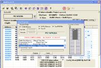
now it is ok...Proteus simulation working well. But I burned the PIC Chip with the hex file, there has an error....and not completed yet....

I think need to config the programme memory....


Manoj, do you have possibility to use other programmer?
try to find some other PIC programmer, from some collegues...
regards
 

Manoj, do you have possibility to use other programmer?
try to find some other PIC programmer, from some collegues...
regards


Hello Peter,

Some chips programmed with my lynx bios programmer and its working well. In this case, I get some error message. Is the problem of hex file or the chips? The PIC16F676 is programmed only one time programmeble chips?

regards
 

C series chips like PIC16Cxxx are one timer programmable. F series are flash and can be re-programmed. See if you have previously locked the chip. Code Protect is enabled?
 

Manoy,
hex file is not a problem,
you have problem with programmer or MCU
regards

p.s. Manoy,
I read in your previous posts many mcu:
you start with 12F628A, probably this is tipe error,
sch. show 16F628A, that is Ok,
I build hex file for you with 16F628A, with external osc at 10MHz,
in the last post you say 16F676,
please specify what is correct....


Sorry for my Mistakes.

Its 16F628A. That correct.

I try to build a digital voltmeter with PIC16F676. Sometime I confused....Its my Mistake and Sorry.( I am new in PIC. Can you please help me to build a Digital voltmer with PIC16F676 ? .The shematic in the coolcircuit is not working. I have a working Model and I buy from market. Can you please?

can I attached the schematic and the proteus file, which I Trace from the working Model?
 

Zip and attach the Proteus file and mention the Clock freq and PIC used. I will compile the code for the other chip after checking the datasheet.
 

Zip and attach the Proteus file and mention the Clock freq and PIC used. I will compile the code for the other chip after checking the datasheet.

Zip and attach the Proteus file and mention the Clock freq and PIC used. I will compile the code for the other chip after checking the datasheet.

Thanks Jayanth.......

Finally I am making the 3 Digit Voltmeter.....Great stuff for me. and Thanks to attenssion about my request......*** BLESS YOU ALWAYS.


regards
 

Mention PIC that will be used and also Clock freq (OSC) used? External or Internal OSC?

Hi Jayanth.....

My 3 Digit voltmeter working perfectly.... So I have the new problem...I need an AC Voltmeter for 0-300 V measuring. I seeave the circuit and the Working Model. I dont have the hex file.... Can you please and see the attachment.

Regards
 

Attachments

  • ISO-8859-1__ac-volt_1255-001-001.jpg
    ISO-8859-1__ac-volt_1255-001-001.jpg
    112.9 KB · Views: 123

Convert ans scale your ac to dc 5V.

HTML:
#include <16F676.h>   
#device adc=10    
#fuses INTRC_IO,NOWDT,PUT,NOPROTECT,BROWNOUT,NOMCLR   
#use delay (clock=4000000) // 4MHz clock   
   
#rom  0x3ff={0x3444}   
   
#byte PORTA = 0x05   
#byte PORTC = 0x07   
#byte TRISA = 0x85   
#byte TRISC = 0x87   
   
#define SPORTA PORTA   
#define SPORTC PORTC   
   
#define  TICKS_BETWEEN_INTERRUPTS      5000 //5000   
#define  INTERRUPT_OVERHEAD            35   
#define  TMR1RESET (0xFFFF-(TICKS_BETWEEN_INTERRUPTS-INTERRUPT_OVERHEAD))   
   
const char SegCode[11] = {0x40,0x57,0x22,0x06,0x15,0x0C,0x08,0x56,0x00,0x04,0xFF};   
    //                       0    1    2    3    4    5    6    7    8    9   
const char Column[3]   = {0x02,0x01,0x04};   
static char Segment[3] = {0x7f,0x7f,0x7f};     
static unsigned char ColCount=0x00;   
   
void CPU_SETUP(void);   
void Display(void);   
void HTO7S(unsigned int32 Num);   
   
byte i;   
unsigned int32 result;   
   
#INT_TIMER1   
void Timer1(void)   
{      
    set_timer1(TMR1RESET);   
    Display();     
}      
   
void main()   
{          
    unsigned char i;   
       
    CPU_SETUP();   
       
    while(true)   
    {              
        result=0;   
        for (i=0;i<20;i++)   
        {   
            set_adc_channel(3);    
            delay_ms(1);    
            result=result+read_adc();   
        }   
            //result = 0x3fe;                                      
        HTO7S(result/20);      
        delay_ms(200);             
    }   
       
}   
   
void CPU_SETUP()   
{   
       
   setup_comparator(NC_NC_NC_NC);   // not use comparator module   
   setup_adc_ports( sAN3 | VSS_VDD);    
   setup_adc(ADC_CLOCK_DIV_64);   
   TRISA=0b00011000;   
   PORTA=0x27;   
   TRISC=0b00000000;   
   PORTC=0x37;   
      
      
   setup_timer_1(T1_INTERNAL|T1_DIV_BY_1);   
   set_timer1(TMR1RESET);   
   enable_interrupts(GLOBAL);   
   enable_interrupts(INT_TIMER1);      
}   
   
//-------------------------------------   
// Display routine   
//-------------------------------------   
void Display()   
{   
    PORTA = 0b00100111;   // off all digits column and Segment G   
    PORTC = 0b00111111;   // off segment a-f       
    delay_cycles(2);   
       
   
    if (ColCount>=3)    
    ColCount=0;   
           
    SPORTC = Segment[ColCount];   
    SPORTA = ((Segment[ColCount] & 0b01000000)>>1) | (Column[ColCount]^0x07);   
    ColCount++;                
}      
   
//--------------------------------------   
// Convet HEX 2 byte to 7-Segment code   
//--------------------------------------   
void HTO7S(unsigned int32 Num)   
{   
   
    unsigned int32 res;   
   
       
    Segment[0]=SegCode[30*Num/10230];   
    if (Segment[0]==0x40)    
    Segment[0]=0xFF;   
       
    res = 30*Num%10230;   
    Segment[1]=SegCode[10*res/10230];   
    res=10*res%10230;   
    Segment[2]=SegCode[10*res/10230];   
}


Is this the code for the AC 230 V meassurment?

can you give me the hex file for this code? I dnt knw that...Please...


I Think this is the right cod efor the above circuit

regards
 
Last edited:

Status
Not open for further replies.

Part and Inventory Search

Welcome to EDABoard.com

Sponsor

Back
Top