Continue to Site

Welcome to EDAboard.com

Welcome to our site! EDAboard.com is an international Electronics Discussion Forum focused on EDA software, circuits, schematics, books, theory, papers, asic, pld, 8051, DSP, Network, RF, Analog Design, PCB, Service Manuals... and a whole lot more! To participate you need to register. Registration is free. Click here to register now.

Trying to identify these 3 types of waveguides

Status
Not open for further replies.

unlucky

Newbie level 5
Joined
Jul 11, 2013
Messages
8
Helped
1
Reputation
2
Reaction score
1
Trophy points
3
Location
Hillsboro Beach, FL
Activity points
81
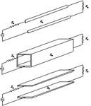
I am just beginning and required to learn something on waveguides. Can someone tell me what these 3 types of waveguides are? Is one of them 'rectangular'? After knowing this, I will hope to be able to describe the differences between these 3 transmission means in terms of the frequency response, from zero to infinity. waveguides.png
 
Last edited:

frequency response from zero to infinity should be obvious by inspection! U really do not know?

For instance, what would a voltmeter read for low frequencies in the middle figure???
 

frequency response from zero to infinity should be obvious by inspection! U really do not know?

For instance, what would a voltmeter read for low frequencies in the middle figure???

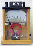
old voltmeter.png


Here is a volt meter. It reads 5V in the middle. I'm sure you had something else in mind. But like I said I'm new to waveguides. To answer your question, no, I do not know and what's so obvious to you about frequency response from zero to infinity will hopefully be obvious to me soon enough. I look at the 3 types of waveguides I posted and still don't know what is going on. That's why I ask. I'm no expert; just a beginner. This is only my first post. Maybe you could explain. Thanks.
 

First i would recommend you to read a good textbook on basic electromagnetism and microwave technology.
I can offer you an explanation of the picture but you will bring more questions.

In the picture, the first is a "twin-line" transmission line. It is a symmetrical structure that can transmit from DC to a very high frequency in TEM mode. When the wavelength approaches ~ 4...6 distances between the conductors, the line radiates.

The second in the picture is a rectangular waveguide. It clearly shorts any DC, ad can transmit wavelengths that can "fit" inside. Depending on the propagation mode we define the "cut-off" frequency. Only this and higher frequencies can propagate. The lowest cutoff is for TE10 mode. At frequencies higher than the dominant mode, loss occurs due to higher modes and the fact that exciting such modes and collecting their energy becomes difficult.

The bottom in picture is the "parallel-strip" structure,similar to the first. Such structure modified by a curvature is a good conductor in THz technology.

I bet you will bring may questions. Start to study first, to understand the basics.

- - - Updated - - -

Concerning your question with a voltmeter: Read the basics!!! Become an expert, otherwise you are lost!
 
Now that helps. I only started to find out what waveguides are a day ago. I will take your advice and read up on the basics. But I'd decided that I'd do so before. Thoughts concerning basic electromagnetism is something I always think about ever since I read my first book on it 30 or so years ago and I’ve read more since. But you are right in that I will have more questions. BTW, I don’t think I had any questions about a voltmeter.

Here are some initial questions I will be asking at least to myself: Did I phrase my original question wrong? My question was “Can someone tell me what these 3 types of waveguides are?” But now I ask myself if they are all, in fact, waveguides. You said the first is a "twin-line" transmission line. Am I to assume this is not a waveguide? I know the second is a rectangular waveguide. Lastly, am I to assume that the third "parallel-strip" structure is not a waveguide? I have a lot to find out. But I must first know, and hopefully will soon find out, is if I will be researching ‘transmission lines’ and ‘parallel-strip structures’ along with waveguides.

Once the above is resolved I will hope to have reached the point I originally posted, where I will be able to describe the differences between these 3 transmission means in terms of the frequency response, from zero to infinity.
 

I've started to view the first of all of those links. They look interesting. I was at it all day yesterday as far as reading about waveguides and transmission lines.
 

Please take another look at the picture in my original post where I explained I was trying to find information that would help me describe the DIFFERENCES of their frequency responses from 0 to infinity for each of the 3.

So far I'm told that the following are:
1. a "twin-line" transmission line 2. a Rectangular waveguide 3. a Dielectric slab waveguide and/or "parallel-strip" structure.

Understanding the basic concept of frequency response and transmission lines and the concept of waveguide (so I think) over the last 4 days, mostly on wiki, I would have to think that what I was asked is that each has its limitations with respect to one another. But I have to admit I only understand the basic equations of the transmission line. As I read on it gets more complex and I lose my grasp.

I ask once again, how can I describe "What are the differences of the frequency responses from 0 to infinity for each of the 3? I'm sorry but I just can't find the information out. I know I'm staring the answer right in the eye but I just can't. I don't mean to convey my frustrations but I'm frustrated. Due to my lack of knowledge in this area, I think I will only understand the question in specific term only if I see the answer. If someone wants to hit me over the head with a sledgehammer I'll accept that too.
 

if you ignore real-world parasitic effects, and concentrate only on 1st order effects:

1) DC to Infinity frequency, since a transmission line works at all frequencies. In the real world, if the spacing between the lines gets too big compared to a wavelength, then all bets are off.

2) Microwave frequency to inifinity. Infinity? Can u shine a flashlight thru it and see the light on the other side? yes. Microwave, look up rectangular waveguide in any text book. DC (and other low frequencies), no because if you connect the two leads of a power supply to the metal walls at one end, and apply the two probes of a voltmeter at the other end, you will read zero volts (and maybe smoke a power supply or two).

3) same as 1) above
 

Status
Not open for further replies.

Part and Inventory Search

Welcome to EDABoard.com

Sponsor

Back
Top