Continue to Site

Welcome to EDAboard.com

Welcome to our site! EDAboard.com is an international Electronics Discussion Forum focused on EDA software, circuits, schematics, books, theory, papers, asic, pld, 8051, DSP, Network, RF, Analog Design, PCB, Service Manuals... and a whole lot more! To participate you need to register. Registration is free. Click here to register now.

[SOLVED] LPC2138 ADC0.0 Simulation Problem in Proteus??

Status
Not open for further replies.

xpress_embedo

Advanced Member level 4
Joined
Jul 5, 2011
Messages
1,154
Helped
161
Reputation
396
Reaction score
189
Trophy points
1,353
Location
India
Activity points
10,591
Hello!! i am using LPC2138 to do some experiment with ARM.
Started with LPC2138 Because it is available in Proteus.

Had write the codes for LCD, UART and LED Blinking but the problem i am facing with ADC is that, it working well in Keil Simulator.
But when simulating it in Proteus, is creating a problem.

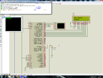
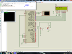
Like when i connect POT-HG with P0.27 i.e A0.0 of LPC2138, my lcd doesn't show anything and an error appears in the Proteus Simulation Window.

ADC_Problem_1.png

But when i disconnect the POT-HG data on LCD Appears properly, why it is so. this is really weird behavior by Proteus.
Please help me if i am doing some thing wrong.

ADC_Problem_2.png

The code is as follow:-
I had not posted the full code but the modules are posted and i think which are sufficient.

Code C - [expand]
1
2
3
4
5
6
7
8
9
10
11
12
13
14
15
16
17
18
19
20
21
22
23
24
25
26
27
28
29
30
31
32
33
34
35
36
37
38
39
40
41
42
43
44
45
46
47
48
49
50
51
52
53
54
55
56
57
58
59
60
61
62
63
64
65
66
67
68
69
70
71
72
73
74
75
76
77
/*****************ADC Functions***************/
void ADC0_Init(void)
{
    /*************Initialize ADC AD0.0*************/
    AD0CR = 1<<21;                              //A/D is Operational
    AD0CR = 0<<21;                              //A/D is in Power Down Mode
    PCONP = (PCONP &0x001817BE) | (1UL<<12);
    PINSEL0 = 0x00;
    PINSEL1 = 0x00400000;                   //P0.27 is Configured as Analog to Digital Converter Pin AD0.0
    
    AD0CR = 0x00200401;                     //CLKDIV=4,Channel-0.0 Selected,A/D is Operational
    /*
    A/D Clock = PCLK /(CLKDIV+1);
    */
    /**********************************************/
}
 
unsigned int ADC0_Read(void)
{
    unsigned long adc_data;
    
    AD0CR |= 1UL<<24;                           //Start Conversion
    do
    {
        adc_data = AD0GDR;
    }while(!(adc_data & 0x80000000));
    //Wait untill the DONE bits Sets
    AD0CR &= ~0x01000000;                   //Stops the A/D Conversion   
    
    adc_data = adc_data >> 6;
    adc_data = adc_data & 0x3FF;    //Clearing all other Bits
 
return (adc_data);
}
 
 
/*********************************************/
unsigned long adc_data;
 
int main()
{
    unsigned char msg[] = "EMBEDDED LAB";
    unsigned char adc_example[] = "ADC EXAMPLE";
    unsigned char data_received[] = "ADC VALUE:";
 
    
    Lcd_Init();
    UART0_Init();
    Delay_ms(10);
    
    UART0_Write_Text(msg);
    UART0_Write(10);
    UART0_Write(13);
    Lcd_Write_Text(msg);
    Lcd_Cmd(SECOND_ROW);
    Lcd_Write_Text(adc_example);
    UART0_Write_Text(adc_example);
    UART0_Write(10);
    UART0_Write(13);
    
    Delay_ms(1000);
    Lcd_Cmd(LCD_CLEAR);
    Lcd_Write_Text(data_received);
    Lcd_Cmd(SECOND_ROW);
    
    ADC0_Init();
    while(1)
    {
        adc_data = ADC0_Read();
        adc_data = adc_data*3300;
        adc_data = adc_data/1023;           //Value of Voltage in Milli Volts
        Display_Number_Lcd(2,1,4,adc_data);
        Lcd_Write('m');
        Lcd_Write('V');
        Delay_ms(10);
    }   
}


Most Important thing i noticed, there is some problem with Enable Pin of LCD, it is not showing led dot in-spite of that it is showing grey mark when pot-hg is connected, otherwise it is okay.
Enable pin is associated with Analog to Digital Converter 0


Please help me
 

Here is the attached file,
Please help me.

When POT-HG is disconnected, LCD Display is okay.
But When Connected, it is not, EN pin is not high..


View attachment ADC.zip
 

It is working fine. Just go to power rail configuration and set VCC as 3.3V.

92591d1371741963-lpc2138.png


92592d1371742385-lpc2138a.png
 

Attachments

  • lpc2138.png
    lpc2138.png
    268.9 KB · Views: 303
  • lpc2138a.png
    lpc2138a.png
    269.9 KB · Views: 254
Last edited:
  • Like
Reactions: xpress_embedo

    xpress_embedo

    Points: 2
    Helpful Answer Positive Rating
    V

    Points: 2
    Helpful Answer Positive Rating
Thanks sir...

I had to Configure the Power Rails and set Vcc=3.3V and apart from that i had to connect supply to LCD also.

Whats the logic behind this.
Why we had done this.
 

Status
Not open for further replies.

Part and Inventory Search

Welcome to EDABoard.com

Sponsor

Back
Top