Continue to Site

Welcome to EDAboard.com

Welcome to our site! EDAboard.com is an international Electronics Discussion Forum focused on EDA software, circuits, schematics, books, theory, papers, asic, pld, 8051, DSP, Network, RF, Analog Design, PCB, Service Manuals... and a whole lot more! To participate you need to register. Registration is free. Click here to register now.

Current Limiter-is it even needed

Status
Not open for further replies.

rahdirs

Advanced Member level 1
Joined
May 22, 2013
Messages
424
Helped
93
Reputation
192
Reaction score
91
Trophy points
1,308
Location
Mordor
Activity points
4,492
Does this mean my circuit works only at 50A current ???????

Hi,

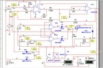
I have a varying voltage source(5 - 15 V) in my circuit.In software,when running simulations i see that very high currents of 40 -50 A are coming out from it,but when i'm going to implement the circuit,my source has a maximum output current of 10 A.So,it isn't an issue right,it's just that my source is incapable.When i design circuit on PCB it should work alright ???

But i wanted to keep limit current to 10 A & see if my circuit works alright.I used current limiter block available in Multisim. I kept it just after source.Then i found that current at o/p of current limiter doesn't go beyond 10 A,but now the voltage at the o/p of current limiter isn't rising above 7 V.

Does this mean if i connect my circuit to the source,it can give 10 A max.Will my circuit prevent source voltage to go above 7 V ???
 

Re: Does this mean my circuit works only at 50A current ???????

A common method of current limiting is that if the current draw approaches the current limit setting , the output voltage
of the supply starts to fall , until the falling voltage causes the current to drop below the limit once again.
For instance. Suppose you have a 10V supply that can supply 1A (current limit of 1A). If you connect a 5 ohm resistor
to it , it will drop it's output voltage to 5V , and so deliver 1A once again. If you have an active load that does not draw current
in a "linear" fashion , the voltage that the supply will drop to could be difficult to determine.
Cheers
Neddie
 
  • Like
Reactions: rahdirs

    rahdirs

    Points: 2
    Helpful Answer Positive Rating
@neddie: Yeah, my issue is my circuit is taking 50 A from source,but source that i'm to use in design has 10 A max. current.So my source is incapable to provide 50 A current,but the circuit should work.

Basically i kept transistor in darlington configuration that is drawing high current.If source is only capable of providing 10 A,the transistor should only pass 10 A & circuit should work alright.
 

If the source is only capable of supplying 10A and your circuit tries to draw more than 10A , the source output voltage will start to fall. If your circuit only draws 10A
, then all's going to be ok.
 

If 50A is a transient then perhaps the filter bank takes
that up and the average current limit is still met. If 50A
is an extended duration startup event, then you could
get hung up if there's any metastable point (like, say,
a power stage in cross-conduction making a current
"spike" you can't get over on a slow ramp).

You want to understand this better along with the
true nature of the current limit mechanism.
 
Where is that high current going?

This discussion would be a lot easier if you posted the circuit schematic.
 

This discussion would be a lot easier if you posted the circuit schematic.
The circuit is messy, i kept on adding components & i didn't arrange them in any order.
But,still i attached it.
I don't think the problem with the circuit is i just need to replace those transistors in darlington configuration to ones that are allow less current to pass
**broken link removed**
 

Your attachment doesn't work.

Messy circuits make it difficult to understand. Take the time to arrange it in an orderly fashion and you'll be much less likely to make drawing mistakes.
 

@crutschow: you mean to say my circuit doesn't work or you can't see my attachment.I attached it again.

I think if i change darlington transistors to less current capable ones,it should b fine.
See i changed the original darlington configuration of BD 243 transistors to 2N3055 darlington pair & i get less current.
 

Attachments

  • Capture.JPG
    Capture.JPG
    84.2 KB · Views: 77
  • Capture.JPG
    Capture.JPG
    80.8 KB · Views: 70
Last edited:

Your previous link didn't work.

If you truly need a limiter, and I'm not convinced that you do since I don't know where all that current is going, then using a smaller transistor is a poor way to do that because of the large variation in gain between different transistors of the same type. Better to use a dedicated limiter circuit.
 

@crutschow: You see i have just one problem,even i don't think that i need a current limiter circuit.The darlington configuration transistor pair in 2nd can allow a max. of 10 A at that base current. So, i think you can see 1:2 transformer over there.So,as pair can allow 10 A max. the transistor is taking in 20 A from source.

Source in schematic can provide 20 A because it is ideal without dropping any voltage,but my source can only provide 10 A.So if i directly use this circuit will any voltage drop/ the transistor pair take only 5 A????

I am thinking that if source can provide 10 A, at secondary current is 5 A.So,will darlington pair take 5 A from 15.5 V source attached to it & another 5 A from transformer.Is this possible???
 
Last edited:

I was born in the 1950s and worked in electronics since I was 14 years old, I've worked on some World scale development projects but I still can't work out what that schematic is trying to do. :-?

Brian.
 

I was born in the 1950s and worked in electronics since I was 14 years old, I've worked on some World scale development projects but I still can't work out what that schematic is trying to do. :-?
You still haven't explained where all this current is going. :?:
I apologize for the delay,but the time-zone difference.I'll try to organize the schematic & re-post it.
But, i'll explain it a bit/what i did before trying to post the schematic.
  • I have a PSU(the 18.5,15.54,9 V batteries you see are from PSU) & a varying voltage source.
  • Firstly using the two op-amps at the top i made the varying voltage source voltage constant using PSU (subtractor & adder).
  • Then i get the o/p of adder as 15 V (almost constant) & current at 30 mA(max.)
  • Then i give this to the base of a transistor connected in darlington configuration.So,the input to the base of transistor is 15V , 25mA.
  • I connect the emitter to a battery(there's no charge controller but i'll use it).So the current that flows into battery must come from collector & base.
  • The collector should be at 15 V for it to operate in active region.The current coming through collector would depend on beta & base-current.That current is in range of10-15A.
  • So at collector i have 15V & 10 A current flowing in.
So,where is that current coming from ????
Since the collector must be at at least 15 V.I used it to switch between three sources.


1)When the voltage of the varying source is less than 9 V,i supply current from PSU (15.54 V source before schottky diode at bottom end).
2)If the voltage of varying source is greater than 15 V,PSU stops supplying current & current comes from varying source.
3)If the voltage is in between 9 - 15 V,i used a 1:2 transformer to make the voltage to at-least 15 V.The current flows from this path if voltage is in between 9-15 V.


-------------------------------------------Updated after 30 min------------------------------------------------------
I attached the schematic after re-arranging the components in this post.
 

Attachments

  • Capture.JPG
    Capture.JPG
    245.9 KB · Views: 64
Last edited:

I'm still not sure exactly what you are trying to do here. I think it's supposed to be a battery charger of some sort:0/
You should definitely not use you component characteristics (ie: transistor hfe) to limit current.
Build a proper current monitoring and limiting circuit. You seem to be over complicating things here. How is
transformer T1 supposed to work? I only see dc supplies scattered around? I get the feeling your a little out of your depth here!
Neddie
 

I think it's supposed to be a battery charger of some sort:0/You should definitely not use you component characteristics (ie: transistor hfe) to limit current. Build a proper current monitoring and limiting circuit.How is transformer T1 supposed to work? I only see dc supplies scattered around?

I've already said that i'll use a charge controller & all.
Oh,regarding my usage of transformer with DC(that i need a changing magnetic flux to get o/p)& all. I've just added that part yesterday.I need to remove it & replace with a DC-DC converter(maybe buck-boost).
My schematic isn't complete,i've just attached it so that ppl may understand it better & i wasn't even asking how do i do DC-DC conversion.:x

My only question from the beginning of the thread is if a transistor is taking 10 A of current from sources connected to collector to supply it to load connected at emitter.If one source is only capable of providing 5 A,can the other source provide other 5 A ???? Or does the source voltage drop.
I should've never posted schematic & instead just attach the below image
 

Attachments

  • Untitled.png
    Untitled.png
    7.3 KB · Views: 63
Last edited:

You can connect as many sources as you want to the collector of the transistor. The transistor does not care. You may have issues with the different sources fighting each
other if they are not properly matched , but that does not seem to be what you care about at the moment.
If for instance you have a 12V battery as a source and that battery can supply 5A.
If you need 10A , then connect a second battery(of the same type) and you can get 10A. 3 batteries for 15A etc.
Your diagram indicates 25mA base current for 10A collector current. Unlikely in a power transistor (hfe of 400) , but an even worse idea to rely on that as your current limiting
feature. As your transistor heats up , and it will when conducting 10A , the hfe is going to change significantly.
Neddie
 

In that small diagram transistor was equivalent of two transistor in darlington configuration.So equivalent ß was ß1*ß1 = ß1^2.

So,in those sources battery can easily supply 10 A required.
Source 2 can only supply 5 A.So,the battery will supply remaining 5 A right
 

Correct.
You are going to have to pay attention to your "Sources". You can't just parallel at will :0)
If you have 1 source that is 12V and another that is 15V , you may have a problem. The 15V source is
going to be doing all the work , if it can supply the full current. If it can't , it will supply what it can and it's output will probably
drop. If it drops to 12V , then the other 12V source will kick in and also start to supply some of the current.
It's also possible that the 15V source could damage or blow up the 12v source , depending on the hardware.
There are a lot of unknowns here :0)
 

The new schematic will not work and I fear the theory behind it's operation is flawed. I understand what Rahdirs is trying to do but I don't think it will ever work. If I may draw an analogy, it's like trying to produce 12V at high current from an AA cell, it may work for a short time but the notion that as the cell voltage drops you can just draw more current from it to keep the output power up is clearly not going to work. Rahdir is working on the principle that as the voltage from his PV panels falls as it gets dark, they can draw more current from them to maintain output. A PV in partial light is rather like the AA cell in my anaolgy, if it can't maintain voltage it's because it can't cope with the load already on it and trying to extract more will not work. Several of us have tried to explain MPPT but to no avail.

Brian.
 

Status
Not open for further replies.

Part and Inventory Search

Welcome to EDABoard.com

Sponsor

Back
Top