Continue to Site

Welcome to EDAboard.com

Welcome to our site! EDAboard.com is an international Electronics Discussion Forum focused on EDA software, circuits, schematics, books, theory, papers, asic, pld, 8051, DSP, Network, RF, Analog Design, PCB, Service Manuals... and a whole lot more! To participate you need to register. Registration is free. Click here to register now.

Multiplexing 7 segment LED display

Status
Not open for further replies.

acicsok

Newbie level 4
Joined
Feb 17, 2013
Messages
6
Helped
0
Reputation
0
Reaction score
0
Trophy points
1,281
Activity points
1,349
Hi,
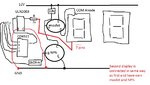
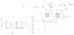
After a lot of searching, I have found some similar threads but not the solution for my problem. I have two 2.3" common anode displays and I want to multiplex them and I made some circuit but it don't work. The problem is that displays are blinking, refresh rate is 60 Hz measured few times. P-channel mosfet for high side switching is BS250 and NPN transistor is 2n3904. Sorry for my bad English and I am hoping that someone can read my schematic that is attached on post.
Thank you for help.
P.S. Microcontroller is used to drive all elements.
 

Attachments

  • simple shematic.jpg
    simple shematic.jpg
    102.8 KB · Views: 281

Here is my code. This project is thermometer that read temperature from LM35 analog pin using ADC. Code for reading temperature is good and working as need to. My only problem is displaying this temperature. I am trying but I can not find what is wrong.
One more question, should I leave COM on ULN2003a connected to 12V or this pin must be unconnected?

Code C - [expand]
1
2
3
4
5
6
7
8
9
10
11
12
13
14
15
16
17
18
19
20
21
22
23
24
25
26
27
28
29
30
31
32
33
34
35
36
37
38
39
40
41
42
43
44
45
46
47
48
49
50
51
52
53
54
55
56
57
58
59
60
61
62
63
64
65
66
67
68
69
70
71
72
73
74
75
76
77
78
79
80
81
82
83
84
85
86
87
88
89
90
91
92
93
94
95
96
97
98
99
100
101
102
103
104
105
106
107
108
109
110
111
112
113
114
115
116
117
118
119
120
121
122
123
124
#include <avr/io.h>
#include <avr/interrupt.h>
 
#define Data_Comm PINB0 //pin14
 
#define LED1 PINB6 //NPN led disp. 1 pin9
#define LED2 PINB7 //NPN led disp. 2 pin10
 
#define bitA PIND0 //pin 25, LSbit for 4511
#define bitB PIND1
#define bitC PIND2
#define bitD PIND3
 
#define BCD PORTD
#define MUX PORTB
 
//ATmega 8, 1 MHz
 
volatile unsigned int g_rez = 0, g_isp = 0, g_a = 0;
volatile unsigned char g_z = 1, g_rac=1, g_zn0, g_zn1;
 
unsigned int ADC_rez(void);
void ADC_ini(void);
 
int main( void )
{       
    
    DDRB |= 1<<LED1 | 1<<LED2;
    DDRC |= 1<<bitA | 1<<bitB | 1<<bitC | 1<<bitD;
    MUX &= ~(1<<LED1) & ~(1<<LED2);//NPN turn off (MOSFET gate PULL-UP )
    
    ADC_ini();
    
    sei();
    
    g_isp = ADC_rez()>>1;//ADC result need to divide by 2
 
    OCR1A = 3906; 
    TIMSK |= 1<<OCIE1A; 
    TCCR1B|=(1<<WGM12) | (1<<CS12); //timer1 CTC mode
    
    OCR2 = 130;//Output compare register
    TCCR2 |= 1<<WGM21 | 1<<CS22;//prescaler 8bit timer 2 /64    
    TIMSK |= 1<<OCIE2;
    
    while(1){       
        
        if(ADCSRA & 1<<ADIF){ 
            g_rez = ADC_rez()>>1; 
            ADCSRA |= 1<<ADIF; 
            ADCSRA |= 1<<ADSC;
            }
    
    }


}
 
ISR (TIMER1_COMPA_vect)
{   
    g_a++;
    if(g_a==10)
    {
        g_isp=g_rez;
        g_rac=1;//flag for new value
        g_a=0;
    }
}
 
ISR (TIMER2_COMP_vect)
{
    unsigned char pr=0, dr=0;
    
    if(g_z)
    {
        if(g_rac)//if new value is ready
        {
            pr=g_isp/10;
            dr=g_isp-pr*10;
            g_zn0 = pr;//save first number
            g_zn1 = dr;//save second number
            g_rac=0;
        }
        pr = g_zn0;
        
        MUX &= ~(1<<LED2);//turn off LED disp. 2(right)
        BCD &= ~(0x0F);
        BCD |= pr; 
        MUX |= 1<<LED1;
        g_z=0;
    }
    else
    {   
        dr = g_zn1;
        
        MUX &= ~(1<<LED1);//turn off LED disp. 1(left)
        BCD &= ~(0x0F);
        BCD |= dr; //ispisujem drugu znamenku
        MUX |= 1<<LED2;
        g_z=1;
        
    }
}
 
unsigned int ADC_rez(void){
    unsigned int MSBy, LSBy;
    LSBy= ADCL; // low byte
    MSBy= ADCH; // high byte of 10 bit ADC register
    MSBy= MSBy<<8;
    MSBy |= LSBy; 
    
    return MSBy;
 
}
void ADC_ini(void){
    ADMUX |= 1<<REFS0;
    ADCSRA |= 1<<ADEN | 1<<ADPS1 | 1<<ADPS0; //enable ADC, prescaler: /8
    ADCSRA |= 1<<ADSC; //start conv.
    while(ADCSRA & 1<<ADSC){}
    while(!(ADCSRA & 1<<ADIF)){}
}

 
Last edited:

After some time I found that there is no problem with my code. I have disconnect my mcu from circuit to see what is the problem. When I connect A,B,C and D input of CD4511 IC to ground and bases of NPN tranistors to +5V on segment displays should be number 0 but there is 8 and it blinks. When I touch with my finger resistor between gate and source of p-channel mosfet sometimes display show number 6. I realy dont know what is problem in this schematic it behaves so weird.
I have make new better schematic and I am hoping that someone will help me.
 

Attachments

  • schematic2.jpg
    schematic2.jpg
    669.4 KB · Views: 170

There are several things which may be wrong with your circuit:

1. You're trying to push around 40mA through each LED segment. The power supply is 12V, the LED segment drops about 1.2V, and the resistance is 270 plus 14 for the MOSFET...that's (12-1.2)/(270+14)=38mA. That is way too much. You should only need about 10mA. And with only 10mA you would not need the MOSFET.

2. According to the datasheet for the MOSFET it has a max gate-source threshold of -3.5V. But yours is more like -12V. The 2N3904 is pulling the MOSFET gate down to almost 0V, but the source pin of the MOSFET is at around 12V.

3. I would eliminate the both transistors and just use a 2N3906 PNP.

4. If your power supply can't provide much current you might have problems trying to give each LED 40mA.

But what you should do first is remove the CD4511 and ULN2003, and tie the 270 ohm resistors to high or ground to achieve the "0" to make sure that works. Then add the ULN2003 and tie its inputs to achieve the "0". Then add the CD4511.
 
Your post make me to think. This LED display is 2,3" and I have measured voltage drop per segment and it is 7,5V (4 diodes in series), current through segment is 13 mA.

I checked displeys, ULN2003 and CD4511 like you said and they are fine. Instead of 2N3906 I put BC557, but to turn off that transistor I need at least -0,5V between base and emiter so I am using BC547 to pull PNP base to 0 the sam way I do with mosfet.
Everything is fine when I connect CD4511 inputs to +5V or 0V, npn base over 1K resistor to +5V and corresponding number shows, even when mcu drive npn transistors and cd4511 inputs are fixed to e.g DCBA (0v,0v,5v,5v) numer 3 shows up.

Things go crazy when I connect mcu to ABCD input of cd4511, displays are blinking again.
Video below shows blinking.

 
Last edited:

Oh, okay. Because in post #4 you said that even without the MCU it displays an "8" instead of "0" and it blinks. I was a little confused. I also didn't realize you were using large 7-segment displays.

So does it work fine without the MCU?

If yes, then try putting a 10K (or larger) resistor from the MCU pin to ground. That's if you're using an NPN. If you're using a PNP, then tie the resistor high.
 
Last edited:

I tried some things and found that if I leave unconnected inputs of cd4511, display blinks an if I connect them to ground, display show 0 and don't blink. Whole time mcu is connected to NPN transistors and switching them (switching displays by pulling PNP base low).
Now I know that there is something with inputs of CD4511, maybe in some moment they are floating and because of high impedace on input CD4511 behaves so wierd. I will try to find TTL IC replacement for this CMOS CD4511, maybe this resolve my problem.
 

Check the high and low voltage levels from the MCU on those pins. Compare to the CD4511 datasheet. Is the CD4511 powered by 5V?
 

Voltage levels on BCD pins are 4,8V for '1' and 0,01 for '0', enough to drive CD4511. CD4511 is powered by 5V same as MCU. One more wierd thing that I found is when I bring closer my hand to CD4511 inputs, other segments on display starts to blink.
For now I will leave this project in desk drawer.
If I found a solution for this, I will post it here.
 

Status
Not open for further replies.

Part and Inventory Search

Welcome to EDABoard.com

Sponsor

Back
Top