Continue to Site
Follow along with the video below to see how to install our site as a web app on your home screen.
Note: This feature may not be available in some browsers.
I have already bought the components and three of them are smd, so ill have to use them only now. As you have said i have made a schematic in orcad capture Cis lite. The components used in the schematic are just to show the connections and they do not have footprints associated with them.Hi vinay,
better make it double side because SMD components is used.give the schematic in orcad file format. i will try it in single or double side.double side is costly compare to single side. if you want PCB in single side better use Through hole components.it is easy only
Thanks for the reply. Realized i should try a little more before getting it done from someone
How much will it cost if i get it done ? Will a single sided pcb for the same ckt cost more or a double sided one ? Pcb routing looks very difficult, but i am trying it .
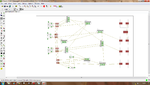
I have started something , so wanted to also know how to go forward with the routing.I am attaching a image of what i have done so far. Here i have a SOIC-8 package MOSFET driver, a smd inductor and smd capacitor
Your post does not have any attachment, so i am guessing that what you have marked is the battery used in the schematic.Yes in place of the battery i need a connector for 12V supply. A normal connector to connect a bench power supply.Like the one showed in the url https://www.ebay.com/bhp/lab-power-supply.Or even jumpers will also be okay.I can then connect power supply with wireshi vinay,
i have one doubt in that i marked in red color rectangular box.is it battery ?? i think it is connector for input supply ,right ? please send the part no ??
I dont know what is the package the KEMET capacitor comes in or if case D is some sort of package ? In eagle i made the footprint using the datasheetfor capacitor which (smd) package do you want ?
It is a very simple design ... you should also try it yourself dear..........you will have fun during the process..... believe me
Kapil please tell me too how do i identify the package of an smd capacitor ? The datasheet of the capacitor says its case D . Is case D a package ?hi vinay,
i have one doubt in that i marked in red color rectangular box.is it battery ?? i think it is connector for input supply ,right ?please send the part no ?? for capacitor which (smd) package do you want ?
yes case D dimensions are there on the datasheet.So is case D the package ?Case D is an IPC standard size. Refer to ipc standard document.
you can also follow the datasheet if you know the part number..
Thanks very much kapilHi vinay,
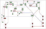
please check the layout file in allegro (you can download the allegro viewer through cadence link: **broken link removed**)
Hi vinay,
if you gerber file(fabrication file) i will send to you.please look at the PCB if you need any clarification let me know.
- - - Updated - - -
Hi vinay,
if you gerber file(fabrication file) i will send to you.please look at the PCB if you need any clarification let me know.
Hi vinay,
it is double side board only.i could not understand where you want connector better mention in layout.for Through hole capacitor part no ??