Continue to Site

Welcome to EDAboard.com

Welcome to our site! EDAboard.com is an international Electronics Discussion Forum focused on EDA software, circuits, schematics, books, theory, papers, asic, pld, 8051, DSP, Network, RF, Analog Design, PCB, Service Manuals... and a whole lot more! To participate you need to register. Registration is free. Click here to register now.

Readind SMS from sim900 gsm module and displaying on LCD using ATmega 128L

Status
Not open for further replies.

Elixyra

Newbie level 5
Joined
May 24, 2013
Messages
9
Helped
0
Reputation
0
Reaction score
0
Trophy points
1,281
Activity points
1,348
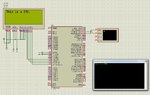
Here are the details:
1)MCU : ATmega 128L
2)Gsm Module: Sim900 module from simcom
3)LCD module: JHD 204A
The code used is:


#include <avr/io.h>
#include <lcd.h>
#include <avr/interrupt.h>
#include <stdlib.h>
#include "uart.h"
#include <util/delay.h>

#define UART_BAUD_RATE 9600 /* 9600 baud */
#define xtalCpu 7372800
unsigned char CtrlZ=0x1A;
int i;
int main(void)
{ int k=0;
char j=0;
char i=0;
uart_init( UART_BAUD_SELECT(UART_BAUD_RATE,F_CPU) );
sei();
lcd_init(LCD_DISP_ON);


uart_puts("AT\r\n");

_delay_ms(3000);
//uart_puts("AT+IPR=9600\r\n");
//_delay_ms(200);
uart_puts("AT+CMGF=0\r\n");//Message format “AT+CMGF=[mode]1”
//[mode] integer type: 0 is PDU mode, 1 is text mode.
_delay_ms(200);
uart_puts("AT+CMGR=1\r\n");// Read Message
while(1)
{i=uart_getc();

//if (i=='+')
//{
//while (s<100)
if(i!=NULL)
{
//c=uart_getc();
lcd_putc(i);
_delay_ms(100);
//s++;
}


}

}
The problem is that I am getting garbage characters on the LCD.The Sim900 module is communicating with mcu using uart. onlt the rx and tx lines are connected. I've checked multiple websites for a similar problem. All seem to be using a similar code.I've used the following library:
**broken link removed**
Please suggest a solution to the display problem. Should i use a different library or are any AT commands available for data transfer from sim900 to Atmega 128L ??
 
Last edited:

Changing the delay did not help. Output is still incorrect

- - - Updated - - -

Sim900 is in autobauding mode. avr-gcc compiler is used.
 

What is the response given by your modem for the command "AT+CMGR=1\r\n"?


Code C - [expand]
1
2
3
4
5
6
7
8
9
10
11
12
13
14
15
16
17
18
19
20
21
22
23
24
25
26
27
28
29
30
31
32
33
34
35
36
37
38
39
40
41
42
43
44
45
46
47
48
49
50
#include <avr/io.h>
#include <lcd.h>
#include <avr/interrupt.h>
#include <stdlib.h>
#include "uart.h"
#include <util/delay.h>
 
#define UART_BAUD_RATE 9600 /* 9600 baud */
#define xtalCpu 7372800
 
unsigned char CtrlZ=0x1A;
 
 
unsigned char msg[] = "";
 
int main(void)
{   
    int k = 0;
    int j = 0;
    int i = 0;
 
    uart_init(UART_BAUD_SELECT(UART_BAUD_RATE,F_CPU));
    sei();
    lcd_init(LCD_DISP_ON);
    
    uart_puts("AT\r\n");
    _delay_ms(3000);
    
    uart_puts("AT+CMGF=1\r\n");//Message format “AT+CMGF=[mode]1” 
 
    _delay_ms(200);
    uart_puts("AT+CMGR=1\r\n");// Read Message
 
    while(uart_getc())
    {
        
        msg[i++]=uart_getc();           
            
    }
    
    i = 0;
 
    while(msg[i++]){
 
        if(msg[i] != '>')
        lcd_putc(msg[i]);
        
    }
 
}


Thanks for the code. But it did not help. still not getting readable output.
 

What are you getting on LCD? Post a video of LCD. If you are simulating in Proteus the post a screenshot. You didn't tell what is the response for the Command I asked in my previous post.
 
On hyperterminal the AT+CMGR gives the message as output. 240520131882.jpg this is the output i get on lcd.
 

i think you have converted the text into ASCII as it is already in ascii
 

Even i think that is the problem...
I am not very sure how to correct it.
The uart_getc() returns 2 bytes. Higher byte is the last received status and lower byte represents byte from ring buffer.
 

Are you sure uart_getc() returns 2 bytes? c in getc is get character and character are 1 byte. When you connect SIM908 to PC and issue "AT+CMGR=1\r\n" Command what is the response you get on HyperTerminal. Just post that response. It will be easy to write the code. You have to use interrupts to receive data properly. Without USART interrupt you will miss some data if some other code is executing.

Try this code.

Code C - [expand]
1
2
3
4
5
6
7
8
9
10
11
12
13
14
15
16
17
18
19
20
21
22
23
24
25
26
27
28
29
30
31
32
33
34
35
36
37
38
39
40
41
42
43
44
45
46
47
48
49
50
51
52
53
54
55
56
57
58
59
60
61
62
63
#include <avr/io.h>
#include <avr/interrupt.h>
#include <lcd.h>
#include <stdlib.h>
#include "uart.h"
#include <util/delay.h>
 
#define USART_BAUDRATE 9600
#define BAUD_PRESCALE ((( F_CPU / ( USART_BAUDRATE * 16 UL ))) - 1)
 
unsigned char msg[] = "";
unsigned int i = 0, j = 0;
 
int main (void)
{
    UCSRB |= (1 << RXEN ) | (1 << TXEN ); // Turn on the transmission and       
 
                //reception circuitry
    UCSRC |= (1 << URSEL ) | (1 << UCSZ0 ) | (1 << UCSZ1 ); // Use 8-bit character 
 
                                //sizes
    UBRRH = ( BAUD_PRESCALE >> 8) ; // Load upper 8-bits of the baud rate value     
 
                //into the high byte
                    //of the UBRR register
    UBRRL = BAUD_PRESCALE; // Load lower 8 -bits of the baud rate value into the    
 
                //low byte of the
                //UBRR register
    sei ()
 
    lcd_init(LCD_DISP_ON);
        uart_puts("AT\r\n");
        _delay_ms(3000);
 
    uart_puts("AT+CMGF=1\r\n");//Message format “AT+CMGF=[mode]1” 
        _delay_ms(200);
        uart_puts("AT+CMGR=1\r\n");// Read Message
    _delay_ms(3000);
    
    for (;;) // Loop forever
    {
        // Do nothing - echoing is handled by the ISR instead of in the main    
 
        //loop
        while(j < 45)
        lcd_putc(msg[j++]);
        j = 0;
        
    }
}
 
 
ISR (USART_RXC_vect)
{
    
    msg[i++] = UDR; // Fetch the received byte value into the variable  
 
            //"ByteReceived"
    msg[i] = '\0';
    if(i == 45) i = 0;      //data length 45 characters.
     
}

 
Last edited:

i detected some error in the module... hyperterminal is not acknowledging the device.
will hav to work on that then i can test this code. Also in the above code the uart registers and vectors hav to be defined according to the library.
Thanks for the suggestion.
 

USART ATMega128, 8MHz. AVR Studio 4.19 Project files + Proteus Simulation attached.

91548d1369556508-sms.jpg
 

Attachments

  • USART.rar
    49.6 KB · Views: 131
  • sms.jpg
    sms.jpg
    267.4 KB · Views: 231
Last edited:

    V

    Points: 2
    Helpful Answer Positive Rating
In the above diagram, the tx pin of sim900 is connected to rx and vice verse. but it has been specified in the sim900 guide that for serial com the rx pin should be connected to rx and same for the tx pin. tx-rx and rx-tx connections are used in debug mode.
 

no there is only one pair.

- - - Updated - - -

This is the application note im referring to.
 

Attachments

  • sim900_serial_port_application_note_v1.03.pdf
    284.2 KB · Views: 115

No. Tx goes to Rx and Rx goes to Tx. It is clearly mentioned in all the diagrams. What are you interfacing to MCU? SIM900 Chip or SIM900 board? If SIM900 Chip then bothe SIM900 and uCs voltage levels should match or you will need a level translator. If you are interfacing SIM900 board to uC or uC board then see if your uc and SIM900 board has RS232 (DB9 Connector). If yes, you can connect using RS232. If not, then Connect Rx and Tx of SIM900 to Tx and Rx of uC.
 

The TX pin goes to tx and same for rx , in case of simple data transfer with sim900. the initial code worked. the problem was with uart buffer size. increasing that to 256 from 32 implemented the code properly. the message was correctly displayed on the LCD after that.
 

Status
Not open for further replies.

Similar threads

Part and Inventory Search

Welcome to EDABoard.com

Sponsor

Back
Top