jayanth.devarayanadurga
Banned
- Joined
- Dec 4, 2012
- Messages
- 4,280
- Helped
- 822
- Reputation
- 1,654
- Reaction score
- 791
- Trophy points
- 1,393
- Location
- Bangalore, India
- Activity points
- 0
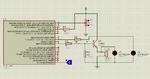
Why this buzzer is not working? I need to drive a buzzer which works like this.
it has 2 pins. One pin is longer than the other. The shorter pin has to be connected to ground and the longer pin has to be given a 2 KH - 4 KHz square wave. It doesn't work if direct 5V is given.
I am attaching my project files. The buzzer doesn't make any sound. My buzzer is a 5V type.

it has 2 pins. One pin is longer than the other. The shorter pin has to be connected to ground and the longer pin has to be given a 2 KH - 4 KHz square wave. It doesn't work if direct 5V is given.
I am attaching my project files. The buzzer doesn't make any sound. My buzzer is a 5V type.