Continue to Site

Welcome to EDAboard.com

Welcome to our site! EDAboard.com is an international Electronics Discussion Forum focused on EDA software, circuits, schematics, books, theory, papers, asic, pld, 8051, DSP, Network, RF, Analog Design, PCB, Service Manuals... and a whole lot more! To participate you need to register. Registration is free. Click here to register now.

What's the highest power possible for a buck converter with Vout = 12V
Status
Not open for further replies.
T

treez

Guest
Hello,

What's the highest power possible for a buck converter with Vout = 12V
 

Your question is too open ended.
If you are willing to synchronize and interleave their switching periods, and you use a load share controller like the UC3907, and your AC mains supply is three phase at 480 volts, and you use active power factor correction, and you have liquid cooling, and........you get the point.....then you can have over 1000 amps.
 
  • Like
Reactions: treez

    T

    Points: 2
    Helpful Answer Positive Rating
Sorry...spec is as follows...

Vin = 24V.
No liquid cooling
Forced air cooling if you must.
No particular size restriction...but want to keep as small as possible.
I am talking of a single stage buck, not several interleaved.
 

What's the highest power possible for a buck converter with Vout = 12V
Hi treez
It depends on what kind of buck converter you're referring to . and what is your load . ( resistive or ... etc ) . and depends on your power switch ! with these low information that you leaved , it is hard to judge .
Best Wishes
Goldsmith
 
  • Like
Reactions: treez

    T

    Points: 2
    Helpful Answer Positive Rating
thanks, ok, can i put it another way........a two transistor forward converter is just an isolated buck converter...they say a two transistor forward converter can do 200W max.........do you think that in the same conditions, the buck can do the same as the two transistor forward converter?
 

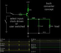
Whatever current goes to the load, also has to get through some amount of resistance in the power loop. (The power loop includes all components which carry the bulk of current during switch-On.)

Say this resistance is 0.3 ohm.
Add your load because it is in the power loop. Say 0.4 ohm. (If it is much lower you can never obtain 12V at the load.)
Say your power supply is twice your specified Vout of 12V. This makes the power supply 24V.

(What part does the smoothing capacitor play? Because it is charged to 12V (Vout), it carries little current. It has only a small role in this instance.)

My simulation shows coil current plateaus at 32 A, at a duty cycle of 95 %.
The coil is acting more like a choke.

The .4 ohm load get 12V at 30 A.
360W.

It is possible to get more power but only at a higher supply V.

 
  • Like
Reactions: treez

    T

    Points: 2
    Helpful Answer Positive Rating
I'm involved with the design of "buck converters" that source or sink up to 1200 A for battery test. Of course this isn't an absolute limit.
(A new instrument generation is air cooled, too)

P.S.: If we are talking about reasonable current range for a single phase buck, we'll possibly end up with a few 100 A. But it will most likely utilize paralled transistors, either multiple chips in a package or multiple individual packages.

You'll also find out, that above a certain current range, multi phase topologies are preferable, resulting in lower overall component costs.
 
Last edited:
  • Like
Reactions: tpetar and treez

    T

    Points: 2
    Helpful Answer Positive Rating

    tpetar

    Points: 2
    Helpful Answer Positive Rating
i would have thought 100A was not feasible for a single stage buck, as every 1 milliohm of resistance (pcb trace resistance etc) dissipates 10W with 100A....so id have thought 100A bucks always need to be a system of parallel bucks?
 

If we work at it, we might manage to cut stray resistance as low as 0.1 ohm. Then it is possible to send over 100 A to the load, at 12V. Then the load can be about 0.1 ohm.

But then notice something...?

It's not much different from dividing down 24V to 12V via resistive divider.

Of course you are not limited to 24V for the supply, but it shows where a buck converter can start turning into a resistive voltage drop.
 
  • Like
Reactions: treez

    T

    Points: 2
    Helpful Answer Positive Rating
does paralleling mosfets count as interleaving?
10 watts of conduction loss at 50% duty cycle is 144 amps through a 1 milliohm fet.

they make them with lower on resistance than that afaik, and seeing as you're delivering 144 amps at 12 volts, your 10 watts loss in the mosfets is negligible.
switching losses at 50Khz should be on the order of 1 watt...
 
  • Like
Reactions: treez

    T

    Points: 2
    Helpful Answer Positive Rating
If we work at it, we might manage to cut stray resistance as low as 0.1 ohm. Then it is possible to send over 100 A to the load, at 12V. Then the load can be about 0.1 ohm.
It's not necessarily so. Do you know that a recent PC processor core power supply involves current in a 100 A range at voltages of 1V and below? Just to highlight state of the art.
 
  • Like
Reactions: treez and tpetar

    tpetar

    Points: 2
    Helpful Answer Positive Rating
    T

    Points: 2
    Helpful Answer Positive Rating
For reference, my motherboard can supply 110ADC to its CPU (up to 1.2V) with just four interleaved phases. So obviously they're able to keep path resistance down to the level of a few milliohms per phase, including FET and inductor resistance. There's no reason 12V at 100A would be a problem with similar technology.

There's no reason you couldn't replace the inductors, and use a motherboard cpu power supply to deliver 12 volts at 100 amps.
the mosfets are likely 30 volt rated or higher, and the 4,6 or 8 phase CPU is probably rated to 16 volts or perhaps 20, but that might be pushing it.
The switches would actually be under lower stress due to the higher duty cycle, the heat would be more evenly spread out to the highside switches.
 
  • Like
Reactions: treez

    T

    Points: 2
    Helpful Answer Positive Rating
The reference to CPU PC motherboards should mainly challenge the "stray resistance" argument. You can in fact realize sub-milliohm resistance levels on suitable designed PCBs and of course with more conventional DC bus bars and plates, too. Besides current density, power density has to be considered separately. In a first order, switching losses are proportional to I * V * tsw * fsw. In so far a 12 V/100 A power supply will have higher losses than a 1.2 V/100 A device.

We can implement kW switchers on a PCB, heatsinks (and inductors, as already mentioned) will be a bit larger than for a PC motherboard.
 
  • Like
Reactions: tpetar

    tpetar

    Points: 2
    Helpful Answer Positive Rating
does paralleling mosfets count as interleaving?
10 watts of conduction loss at 50% duty cycle is 144 amps through a 1 milliohm fet.

they make them with lower on resistance than that afaik, and seeing as you're delivering 144 amps at 12 volts, your 10 watts loss in the mosfets is negligible.
switching losses at 50Khz should be on the order of 1 watt...

Interleaving implies more than one coil, and staggered switching times.

This is different from having two or more paralleled mosfets per coil, which get switched in unison.
 

the question is directed at Treez.

FvM.
how do you figure switching losses will increase by changing the duty cycle from 10% (12v in, 1.2v out) to 50% 24v in 12v out?
assuming inductor current is sufficiently continuous (ripple is less than 30%)
ignore the increased switching losses due to the higher voltage.
 

It's not necessarily so. Do you know that a recent PC processor core power supply involves current in a 100 A range at voltages of 1V and below? Just to highlight state of the art.

It calculates as .01 ohm. That is a remarkable achievement.

In putting together my home power system I realized I had to minimize resistance of:
battery connectors,
cable runs (short as possible),
wire to connector joins.

I drove a 2500 W inverter at 24V.
Then there is maintenance. Crusty deposits materializing out of thin air onto battery connectors. Etc.

To add a switched-coil converter there is also:
wire-to-inductor joins,
inductor ohmic resistance,
the diode(s),
the legs of the mosfet(s), etc.
And the know-how to drive the mosfet to its minimum 'On' resistance, and at fast switching speeds.

Did I leave anything out? There's the entire output stage. It must have clean connections as well. Adequate cable sizing.

I don't doubt there are experts who have found ways to get 100A at 1V, by using strategies which I am not aware of.
 

It calculates as .01 ohm. That is a remarkable achievement.
0.01 Ohm is the load resistance. Switch and conductor resistance can be expected below milliohm.

how do you figure switching losses will increase by changing the duty cycle from 10% (12v in, 1.2v out) to 50% 24v in 12v out?
assuming inductor current is sufficiently continuous (ripple is less than 30%)
ignore the increased switching losses due to the higher voltage.
Switching losses aren't affected by the duty cycle in a first order, neither conduction losses in a synchronous switching converter.

But you hit an important point, the switching losses of a buck converter are defined by input voltage multiply output current. In so far, the CPU voltage regulator design would be good for higher power at increased output voltage.
 

Status
Not open for further replies.

Part and Inventory Search

Welcome to EDABoard.com

Sponsor

Back
Top