neazoi
Advanced Member level 6
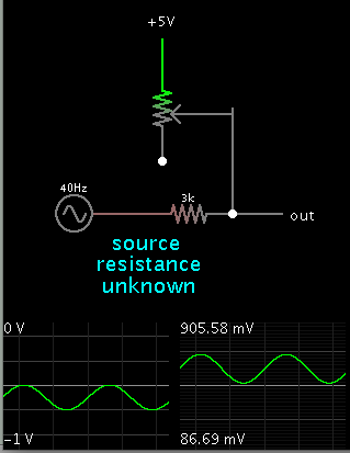
Hi I have a micro with an A/D and I want to use it to monitor a voltage
My application outputs a negative voltage of 0 to -1V and it does not allow to interchange poles, so that I use the GND of the application rail as a positive terminal for the micro.
How should I measure this negative voltage?
My application outputs a negative voltage of 0 to -1V and it does not allow to interchange poles, so that I use the GND of the application rail as a positive terminal for the micro.
How should I measure this negative voltage?