Continue to Site

Welcome to EDAboard.com

Welcome to our site! EDAboard.com is an international Electronics Discussion Forum focused on EDA software, circuits, schematics, books, theory, papers, asic, pld, 8051, DSP, Network, RF, Analog Design, PCB, Service Manuals... and a whole lot more! To participate you need to register. Registration is free. Click here to register now.

Solar Hybrid Inverter

Status
Not open for further replies.

kanni1303

Full Member level 3
Joined
Jun 29, 2012
Messages
164
Helped
12
Reputation
24
Reaction score
11
Trophy points
1,298
Location
Chennai, Tamil Nadu, India
Activity points
2,708
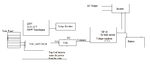
I am doing my project on hybrid solar inverter... i made the inverter to work and used the modles as listed below...

1. Inverter
2. Solar charger.
3. Ac Main charger.
4. battery level indicator.
5. protection unit for Battery.

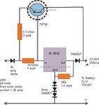
I got the transformer from my old ups and don't know what are the pins...
there are 6 pins on primary i found the phase and neutral but not others...

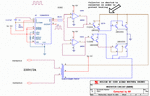
also help me place the switch such that solar power should be used mostly... all the modules working separately fine but dnt know how to add all to one... pls help me...
 

You can't charge the battery directly through AC . Its needs to be step down and convert to DC then only you can charge Battery.

Same procedure for charge the battery from solar panel.

For battery protection high power schottky diodes, or Mosfet

https://www.cutes.com.tw/pdf/solar.pdf

I hope its helps you..
 

i know that... i asked for connecting the each modules as one unit.. ther i lack... independently each module owrking fine... how make all together to make it as one... i prepared one block diagram...

You can't charge the battery directly through AC . Its needs to be step down and convert to DC then only you can charge Battery.

Same procedure for charge the battery from solar panel.

For battery protection high power schottky diodes, or Mosfet

https://www.cutes.com.tw/pdf/solar.pdf

I hope its helps you..
 

Attachments

  • blaock diagram.png
    blaock diagram.png
    14.4 KB · Views: 133
  • Like
Reactions: mjasoj

    mjasoj

    Points: 2
    Helpful Answer Positive Rating
I dont think that will work very well ,the charging is not going to be effective using tip 36 why not mosfet so that you can control the duty cycle going to the gate.
 

**broken link removed** then only selected tip36 for the purpose...
I dont think that will work very well ,the charging is not going to be effective using tip 36 why not mosfet so that you can control the duty cycle going to the gate.

- - - Updated - - -

thanks for your block diagram and the diode between the bridge rectifier and the inverter is compulsory...???

This is the block diagram for how to couple the your module.

If you maintain battery you can use charge controllers.

https://www.ti.com/lit/an/slua115/slua115.pdf

View attachment 89164
 

For starters, your PV modules should be connected to an MPPT charge controller, otherwise you will not be optimizing the power out of the PV modules.
 

Is that MPPT much compulsory what happens if it is not present....

An MPPT charge controller will ensure that you're getting the most out of the PV module. Under any given conditions (temperature, irradiation), there is an optimal voltage and corresponding current to run the PV module at, called the maximum power point (MPP). An MPPT (maximum power point tracking) charge controller will adjust its load (as seen by the PV module) to achieve this operating voltage and current, and will perform a DC-DC conversion to a suitable battery charge voltage.

You can probably get the system working without it, but at reduced output from the PV modules.

Do you have a specific PV module in mind?
 

That regulator Depends on your battery charge rate.

Post your battery capacity and Solar panel rating..

this is having charge controller.

https://www.onsemi.com/pub_link/Collateral/DN06054.PDF

the diode between the bridge rectifier and the inverter its not compulsory that connection is optional.

You are where is in chennai?
 

I made this one from electrical site circuit diagrams... and i planned to power the home so i think 100W is enough and i dont have a idea in PV Module in Specific... I know only theoritical knowledge and interested to do something....

An MPPT charge controller will ensure that you're getting the most out of the PV module. Under any given conditions (temperature, irradiation), there is an optimal voltage and corresponding current to run the PV module at, called the maximum power point (MPP). An MPPT (maximum power point tracking) charge controller will adjust its load (as seen by the PV module) to achieve this operating voltage and current, and will perform a DC-DC conversion to a suitable battery charge voltage.

You can probably get the system working without it, but at reduced output from the PV modules.

Do you have a specific PV module in mind?

- - - Updated - - -

battery capacity 2 ups battery 12V 7Ah, and panel 100W, Yes i am living in chennai... here often power cut is there so i choose the project on that point....

That regulator Depends on your battery charge rate.

Post your battery capacity and Solar panel rating..

this is having charge controller.

https://www.onsemi.com/pub_link/Collateral/DN06054.PDF

the diode between the bridge rectifier and the inverter its not compulsory that connection is optional.

You are where is in chennai?

- - - Updated - - -

While discussing with my teammate he says we need atleast 50Ah battery for using 100W solar panel... i got now only so i found all these circuits will they work with my block diagram and my setup.... i am going to use this for my home after project so planned to proceed with 100 or 75AH battery which ever available... pls tell me... and also overcharge protection and discharge protection i attached... thanks in advance...
 

Attachments

  • 25 amp solar battery charger circuit.png
    25 amp solar battery charger circuit.png
    108.2 KB · Views: 121
  • 500w_220v_inverter_corrected__th.gif
    500w_220v_inverter_corrected__th.gif
    35.6 KB · Views: 142
  • protection.png
    protection.png
    11.3 KB · Views: 103
12 V 100 AH locally available in chennai like ritchie street and Parrys.

If you want branded contact:
AUROW POWER SYSTEMS

#245, (Old # 204), Periyar Pathai,
Choolaimedu, Chennai - 600 094.
Phone +91 - 44 - 2361 4970

They are having 12 V 100 AH battery from Luminas.

Check your PV give what is maximum power. If you are using 100 AH in 100 W PV.

Full battery charging time is take 15 to 20 hours...

We use the PV in 80% efficiency now only it can give maximum life time.

Me also in chennai that's what I'm asking you.
 

I can Buy but i want to do this as my project... anyhow i am going to design only the hybrid inverter and i got that panel and battery alone costs 25K so i negelect both of them and i will show only this alone with what i have... please guide me now with what i can do... i got the components for doing those respectively... i want to do...

12 V 100 AH locally available in chennai like ritchie street and Parrys.

If you want branded contact:
AUROW POWER SYSTEMS

#245, (Old # 204), Periyar Pathai,
Choolaimedu, Chennai - 600 094.
Phone +91 - 44 - 2361 4970

They are having 12 V 100 AH battery from Luminas.

Check your PV give what is maximum power. If you are using 100 AH in 100 W PV.

Full battery charging time is take 15 to 20 hours...

We use the PV in 80% efficiency now only it can give maximum life time.

Me also in chennai that's what I'm asking you.

- - - Updated - - -

so i am not going for this technique....
thnaks for your effort can you suggest me anyother option....

MPPT charge controllers aren't too cheap...

https://www.amazon.com/Morningstar-Sunsaver-TrackStar-Charge-Controller/dp/B006H9VPL6

So probably not worth investing in unless you get up to the 300W PV range.

You might get an extra 30% out of the PV modules with it.
 

I want to design one Hybrid Inverter, and my inverter working details are bellow,
If solar output current is 15Amp, main line should be stand by in charging time.
If solar Output 14 or less then 14 remaining Amp cover from main line, for example " solar output is 12Amp total required Amp is 15Amp remaining Amp is 3Amp so 3Amp cover from mainline.
If load Amp is less then Solar output load need to run from solar current at that time main line will be stand by, or If load is > Solar output then is this condition remaining amp cover from main line, for example solar output 5Amp, running load 13Amp remaining Amp 8Amp so 8Amp will recover from main line.
Is this possible to design this types of circuit, if you know about this please share to me or here... thanks
 

This very simple if you study load sharing in power grids, I think the same concept you are telling,

You want maximum the load should depend on solar and if solar is not available you will move to main line, and this was my concept in doing the project... I used comparator to check for voltage not for amps, since both depends on each other I chose voltage where we can measure it easily and accurately... kindly consider this in your design
 

Status
Not open for further replies.

Similar threads

Part and Inventory Search

Welcome to EDABoard.com

Sponsor

Back
Top