Continue to Site

Welcome to EDAboard.com

Welcome to our site! EDAboard.com is an international Electronics Discussion Forum focused on EDA software, circuits, schematics, books, theory, papers, asic, pld, 8051, DSP, Network, RF, Analog Design, PCB, Service Manuals... and a whole lot more! To participate you need to register. Registration is free. Click here to register now.

[question] problem with real OFDM spectrum

Status
Not open for further replies.

kydong

Junior Member level 2
Joined
Jan 24, 2010
Messages
24
Helped
0
Reputation
0
Reaction score
0
Trophy points
1,281
Location
vietnam
Activity points
1,446
Hi all,

I have trouble with spectrum visualization of OFDM signal.

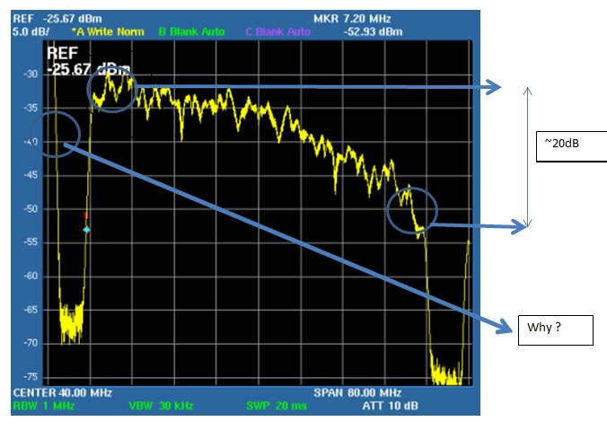
I implemented OFDM system on Stratix II ES180 board and convert the Q-signal to analog via on-board DAC 14bit. I got the result like the figure I attached.
I wonder why the firs edge and end edge of spectrum is far away to each other? the different is large: around 20dB (in the matlab simulation, I got the same level of them)

the second is, there is a mini circuit (transformer) before the DMA output, so, the DC component should be eliminated form signal, why I still get the DC component on the spectrum analyzer (see the figure I attached)

Thanks very much,
 

Do you mean you generated OFDM signal using FPGA and used on-board DAC to convert digital signal to analogue signal. And plot the spectrum using spectrum analyzer?

Did you add Q-component and I-component signals together?
 
  • Like
Reactions: kydong

    kydong

    Points: 2
    Helpful Answer Positive Rating
Do you mean you generated OFDM signal using FPGA and used on-board DAC to convert digital signal to analogue signal. And plot the spectrum using spectrum analyzer?
Yes. I did as you said.
Did you add Q-component and I-component signals together?

No, I just plotted the spectrum of either Q or I component. should I add them before transfer to analog signal for spectrum analysis?
thank you
 

Yes. You should. Let me know if that doesn't work.
 
  • Like
Reactions: kydong

    kydong

    Points: 2
    Helpful Answer Positive Rating
Dear cwjcwj,

I tried, but the result I got is almost the same. I dont think that we should add the real and image component of OFDM signal before plotting spectrum ...

any idea to help me?
thanks very much,
 

1). Do you have a block diagram of how the OFDM signals generated?

2) Do you have a simulation model (Matlab,etc)? If so, try FFT the OFDM signals and have a look on the spectrum.
 

1. I designed it on Matlab simulink, after that, I use the Synphony tool for hardware design and created verilog code.
2. I also checked it on Matlab Simulink. the spectrum of OFDM is flat... not make a angle as viewing on spectrum analyzer.

I wonder maybe the number for FFT in spectrum analyzer is too low? or the buffer number of samples, for example.
 

Status
Not open for further replies.

Similar threads

Part and Inventory Search

Welcome to EDABoard.com

Sponsor

Back
Top