asking
Full Member level 5
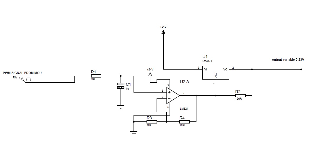
Finally PWM output via low pass filter given to LM324 and i was able to get upto 0-23V per step 0.5Volt increment ") it worked......Thanks...guyz.....Special thanks to Fragrance for the designs....Reference.. The output of the LM324 can be directly connected inplace of Variable of LM317.
it worked......Thanks...guyz.....Special thanks to Fragrance for the designs....Reference.. The output of the LM324 can be directly connected inplace of Variable of LM317.
it worked......Thanks...guyz.....Special thanks to Fragrance for the designs....Reference.. The output of the LM324 can be directly connected inplace of Variable of LM317.