Continue to Site

Welcome to EDAboard.com

Welcome to our site! EDAboard.com is an international Electronics Discussion Forum focused on EDA software, circuits, schematics, books, theory, papers, asic, pld, 8051, DSP, Network, RF, Analog Design, PCB, Service Manuals... and a whole lot more! To participate you need to register. Registration is free. Click here to register now.

[SOLVED] GBW measurement from closed loop buffer connection

Status
Not open for further replies.

Junus2012

Advanced Member level 5
Joined
Jan 9, 2012
Messages
1,552
Helped
47
Reputation
98
Reaction score
53
Trophy points
1,328
Location
Italy
Activity points
15,235
Hello, Nice new week........ Sorry to remind you that the weekend is ended :) :)

Dear friends

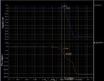
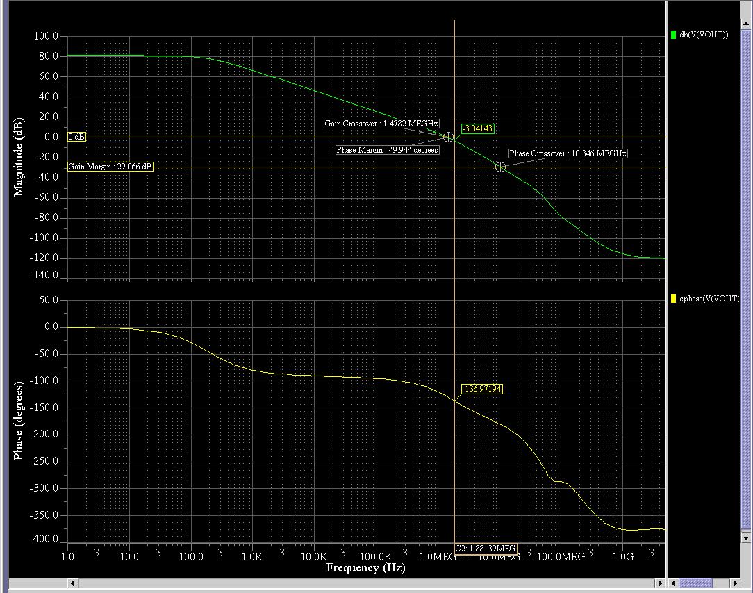
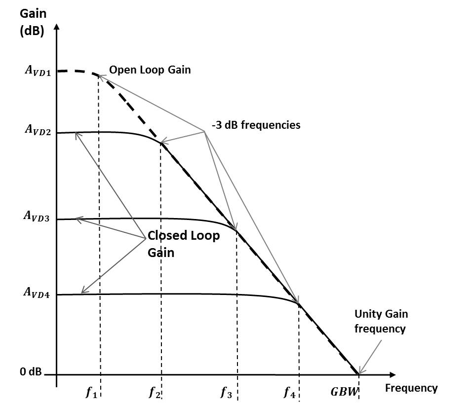
I am trying to find the Gain bandwidth (NOT THE UNITY GAIN BANDWIDTH) from the buffer connection , as usuall, the bandwidth is calculated at -3 dB from the maximum value , so 0-3 dB = -3 dB, in the same time, the phase difference between the output and input is 45

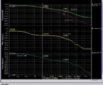
I have connected my designed OTA as a buffer and I run the AC simulation, I got this graph which shoes a different between these assumptions (the -3dB is not when the phase is 45 )

Kindly I am looking for your discussion
 

Attachments

  • buffer.JPG
    buffer.JPG
    186.4 KB · Views: 122

in the same time, the phase difference between the output and input is 45
Only right for a first order closed loop response. Obviously, the shown response is at least second order.
 
Dear FvM

Obviously, in reality there is no first order amplifier, at least at least it is a second order. Then Tell me now How we practically measure The GBW ????

Only right for a first order closed loop response. Obviously, the shown response is at least second order.
 

As you said, GBW is usually understood as the product of closed loop gain and -3 dB bandwidth, without referring to phase.
 

Dear FvM

I have attached you the picture from the open loop response

As you can see, the -3dB frequency from the open loop is different from the one I am getting in the buffer connection, WHY ????
 
  • Like
Reactions: FvM

    FvM

    Points: 2
    Helpful Answer Positive Rating
Junus, I only can refer to FvM`s reply in post#2.
What is your problem?
 

Hello FvM

The problem is there is a difference between the GBW I am measuring from the closed from the Open loop. you can compare between the two pictures I have attached . in the first result the -3dB frequency is 2.3 M Hz. in the second result of the open loop test is giving 1.88 MHZ


Junus, I only can refer to FvM`s reply in post#2.
What is your problem?
 

You are referring to two different measured quantities:

- open loop unity gain frequency
- closed loop bandwidth of +1 amplifier

Although both are related, they don't give the same frequency number at least for a higher order loop gain roll-off. This is due to the fact that a with decreasing phase margin a gain peaking in closed loop result is brought up which extends the -3dB bandwidth. I can hardly imagine that you never came across this effect when looking at OP frequency responses.

You'll apparently find different opinions which of both numbers deserve the title GBW. Systematicly, it should be the open loop unity gain frequency, I think. But the OP theory teachers on the forum can surely tell some plausible points about it.
 
Dear FvM, It is not my fault, all the text book are following to the same picture which I attached , non of them has told there will be a different.

see the picture please


You are referring to two different measured quantities:

- open loop unity gain frequency
- closed loop bandwidth of +1 amplifier

Although both are related, they don't give the same frequency number at least for a higher order loop gain roll-off. This is due to the fact that a with decreasing phase margin a gain peaking in closed loop result is brought up which extends the -3dB bandwidth. I can hardly imagine that you never came across this effect when looking at OP frequency responses.

You'll apparently find different opinions which of both numbers deserve the title GBW. Systematicly, it should be the open loop unity gain frequency, I think. But the OP theory teachers on the forum can surely tell some plausible points about it.
 

Junus, have a look on your own graph in your post#1 (watch the gain peaking) - and compare it with the copied diagram.
You will see the difference.
 
It's nobodies fault to use simplified models e.g. pure first order open loop gain characteristics. They are quite instructive. But don't expect correct results for conclusions beyond the model's validity.

It's quite easy to add a second pole to the open loop characteristic of an ideal OP model and watch how the close loop characteristic changes as the pole is shifted towards the unity gain frequency and phase margin decreases. The experiment should answer all open questions.
 
... all the text book are following to the same picture which I attached ...

Junus - how many textbooks did you consult? Of course, there are good books and also Internet contributions explaining the behaviour of two-pole models with feedback and gain peaking.

- - - Updated - - -

Here is a paper on OTA loop gain (see Fig. 5 and the text below Fig.4).
 

Attachments

  • OTALoopGain.pdf
    427.3 KB · Views: 87
Dear LvW FvM

I totally agree with you regarding the difference between the first and the second order systems. However, if you look at my open-loop response, you will find that the second pole (at 135) is at the zero gain point, which mean that the reponse is behaving like a single pole before it.

As I know that the only difference should be on the roll of amount, after the second pole the roll of is -40 dB and -20 dB before it.

I was believing totally that as soon as the closed loop catch the point of the open loop gain it will follow it exactly as I posted in the graph before.

Any way I did a little investigation and I found :

The closed loop follow exactly the open loop whenever they met until the phase shift becomes more than 90. after this point, the roll of the closed loop gain will be more. Therefore, the concept of the GBW will be only valid at this region.

I have attached you a picture to show my conclusion

Simply it mean that the GBW is only right for the closed loop system if the open loop phase margin is 90, so the second pole must be very far from the unity gain point

I am looking further for your discussion

- - - Updated - - -

Any way I dont find any need to define the GBW from the open loop gain if it can not be applied to the closed loop system if the phase marging is less than 90 which the case of all the practical op-amp
 

Attachments

  • fufu.JPG
    fufu.JPG
    234.4 KB · Views: 97

***
I totally agree with you regarding the difference between the first and the second order systems. However, if you look at my open-loop response, you will find that the second pole (at 135) is at the zero gain point, which mean that the reponse is behaving like a single pole before it.

Yes - before it, more or less. However, you have concentrated on the gain response only, and that´s not sufficient. You have to consider the phase response!
It is easy to show and to verify that the phase margin is approx. only 45 deg for 100% feedback and if the 2nd pole is at the cross-over frequency.

As I know that the only difference should be on the roll of amount, after the second pole the roll of is -40 dB and -20 dB before it.
I was believing totally that as soon as the closed loop catch the point of the open loop gain it will follow it exactly as I posted in the graph before.
Any way I did a little investigation and I found :
The closed loop follow exactly the open loop whenever they met until the phase shift becomes more than 90. after this point, the roll of the closed loop gain will be more. Therefore, the concept of the GBW will be only valid at this region.
I have attached you a picture to show my conclusion
Simply it mean that the GBW is only right for the closed loop system if the open loop phase margin is 90, so the second pole must be very far from the unity gain point
I am looking further for your discussion
Any way I dont find any need to define the GBW from the open loop gain if it can not be applied to the closed loop system if the phase marging is less than 90 which the case of all the practical op-amp

I didn`t completely understand your elaborations and conclusions above. Example: "the roll of the closed loop gain will be more". (???).
Nevertheless, perhaps the following information helps:
*The closed loop gain response NEVER follows EXACTLY the open loop gain response ***. This applies (1) to the non-inverting application and (2) to the asymptotes only (the real curve comes closer and closer only).
*As soon as the phase margin is below 60 deg there will be a gain enhancement (gain peaking) in the region where the loop gain is approx. unity (where the asymptotes meet).

*** I mean: Of course for frequencies where the loop gain<1 (0 dB).
 
Last edited:
Dear, LvW ,, I will take a little time then I will reply you again. this topic brought me a headache... Thank you very much for your response

Yes - before it, more or less. However, you have concentrated on the gain response only, and that´s not sufficient. You have to consider the phase response!
It is easy to show and to verify that the phase margin is approx. only 45 deg for 100% feedback and if the 2nd pole is at the cross-over frequency.


I didn`t completely understand your elaborations and conclusions above. Example: "the roll of the closed loop gain will be more". (???).
Nevertheless, perhaps the following information helps:
*The closed loop gain response NEVER follows EXACTLY the open loop gain response. This applies (1) to the non-inverting application and (2) to the asymptotes only (the real curve comes closer and closer only).
*As soon as the phase margin is below 60 deg there will be a gain enhancement (gain peaking) in the region where the loop gain is approx. unity (where the asymptotes meet).
 

The concept of constant gain-bandwidth-product in fact only applies to the gain range where the open loop frequnecy characteristic can be approximated as first order respectively the phase margin is near to 90°. For unity gain configuration the deviation from first order is probably large, but it will be quite small for gains of 5 and more.

Nevertheless it's a simplification. You can however calculate that a pure first order open loop characteristic results in an exact first order closed loop response and a -3 dB frequency that most exactly corresponds to the unity gain frequency (with a deviation of A/(A+1), where A is the open loop DC gain).
 
Dear FvM, I believe and agree about the GBW is applied for a the first order system, but tell me please, it is very rare to have a phase margin even near to 90. it mean that the GBW can not be applied , but here is the related question,,, why then the companies are providing this value if it cant be used ??????????

In the text references they mention that that if the second pole appear before the unity gain bandwidth, the GBW cann not be use accurately because the diffferent slope of the open loop gain, And they all assume that the closed loop response follow the open loop response at the point when they intersect.

right now I am doing more investigation about this issue, Kindly I have attached you an amazing document from analog device, please you can read a bout the gain bandwidth product which is been in the document in different places
The concept of constant gain-bandwidth-product in fact only applies to the gain range where the open loop frequnecy characteristic can be approximated as first order respectively the phase margin is near to 90°. For unity gain configuration the deviation from first order is probably large, but it will be quite small for gains of 5 and more.

Nevertheless it's a simplification. You can however calculate that a pure first order open loop characteristic results in an exact first order closed loop response and a -3 dB frequency that most exactly corresponds to the unity gain frequency (with a deviation of A/(A+1), where A is the open loop DC gain).

- - - Updated - - -

Hello

please refer to this document as well,(sloa083) he is saying that the GBW is only applied for the voltage feedback amplifier
 

Attachments

  • Edch 1 op amps.pdf
    3.7 MB · Views: 473
  • sloa083.pdf
    114.5 KB · Views: 92

please refer to this document as well,(sloa083) he is saying that the GBW is only applied for the voltage feedback amplifier
Yes, the different properties of CFB amplifiers are discussed in detail in the respective chapter (1.17) of the second literature link. I assume, you are not familiar with CFB, I think they are off-topic for the present discussion.
 
Status
Not open for further replies.

Part and Inventory Search

Welcome to EDABoard.com

Sponsor

Back
Top