ismu
Full Member level 2
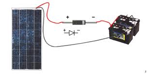
Please check one of solar chager mosfet configration, here lower mosfet connection is ok , but upper is not propper i think (Drain < Sourse even it is a N- channel) . But it is working fine as per the schematic graph [in and out section]. Then How ? I want to explanation about upper mosfet how behave in this circuit? and what the benifit for this connection?