Continue to Site

Welcome to EDAboard.com

Welcome to our site! EDAboard.com is an international Electronics Discussion Forum focused on EDA software, circuits, schematics, books, theory, papers, asic, pld, 8051, DSP, Network, RF, Analog Design, PCB, Service Manuals... and a whole lot more! To participate you need to register. Registration is free. Click here to register now.

bandwidth of the unity gain buffer

Status
Not open for further replies.

Junus2012

Advanced Member level 5
Joined
Jan 9, 2012
Messages
1,552
Helped
47
Reputation
98
Reaction score
53
Trophy points
1,328
Location
Italy
Activity points
15,235
Dear friends

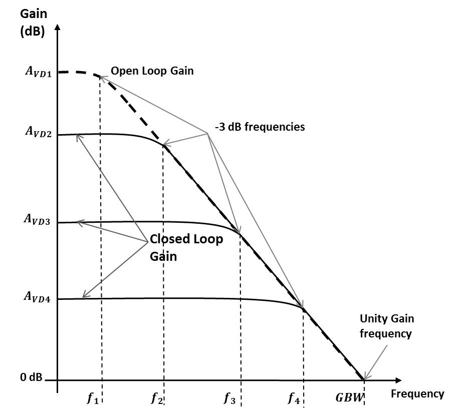
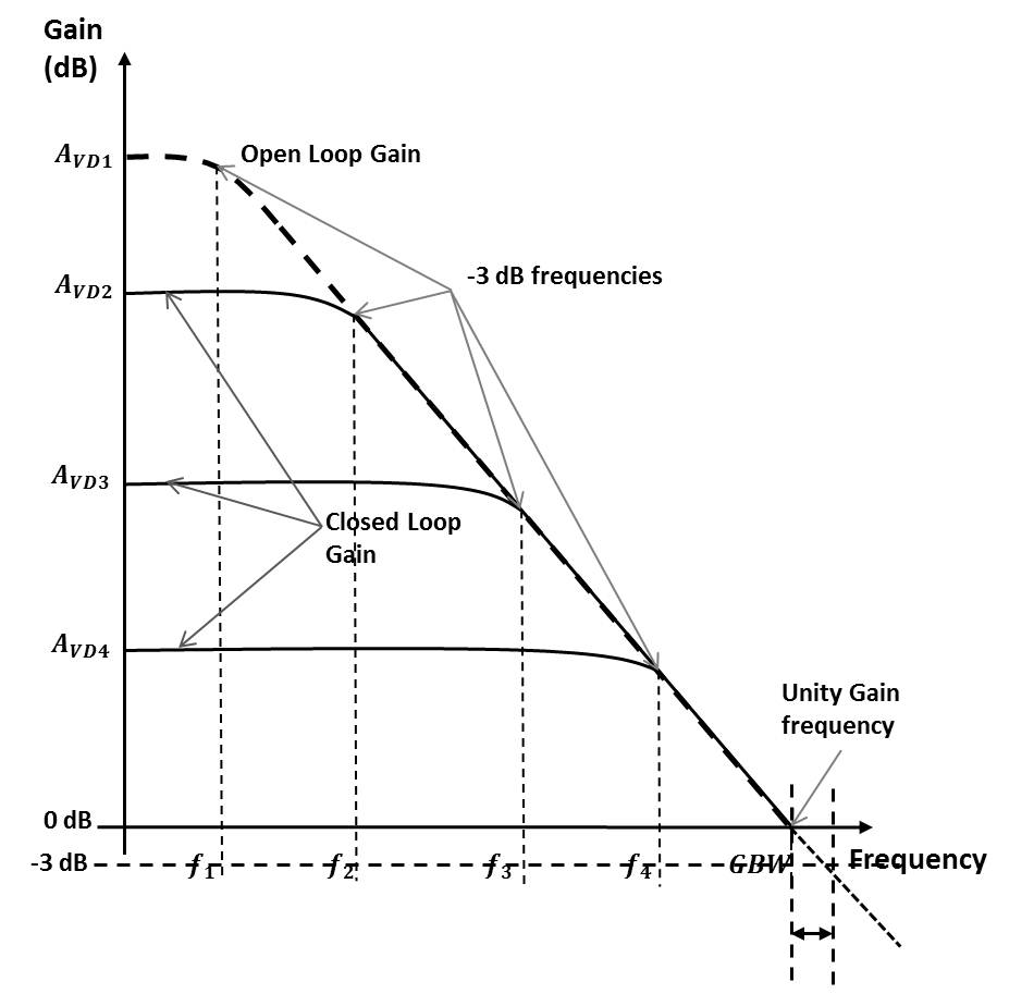
Kindly, why the bandwidth of the unity gain op-amp buffer is defined at the unity gain frequency, while the bandwidth at any different gain is at -3db.

if I apply this principle on the buffer op-amp, then the bandwidth is 0 dB-3 dB = - 3 dB not at 0 dB as from GBW

thank you
 

It is always -3 dB bandwidth that is specified whether it is unity gain or gain greater than one. However, it so happens in a unity gain buffer(non inverting configuration) that the unity gain frequency of the opamp transfer function(open loop transfer function) will be same as the -3 dB bandwidth of the unity gain buffer(close loop transfer function).
 
Could you please show me in any graph th -3 dB frequency of the buffer connected op-amp please


It is always -3 dB bandwidth that is specified whether it is unity gain or gain greater than one. However, it so happens in a unity gain buffer(non inverting configuration) that the unity gain frequency of the opamp transfer function(open loop transfer function) will be same as the -3 dB bandwidth of the unity gain buffer(close loop transfer function).
 

Could you please show me in any graph th -3 dB frequency of the buffer connected op-amp please

Junus - it is very simple:

For any first-order circuit the 3dB point is at a frequency where both imaginary and real part of the denominator are equal. This applies also to the simple RC lowpass.
The denominator of the gain for buffer is D(s)=1/Ao + beta.
With beta=1 (100% feedback) and 1/Ao=j at the transit frequency wt the magnitude of the denominator is SQRT(2)=1.414.
This gives an overall gain drop of -3dB.
(Remember: Open-loop gain approximation Ao=wt/jw )
 
Thanks LvW,

but the gain of the buffer connected start from 0 dB, so I am unable to imagine how the concept of -3 dB is applied here, please see this image


Junus - it is very simple:

For any first-order circuit the 3dB point is at a frequency where both imaginary and real part of the denominator are equal. This applies also to the simple RC lowpass.
The denominator of the gain for buffer is D(s)=1/Ao + beta.
With beta=1 (100% feedback) and 1/Ao=j at the transit frequency wt the magnitude of the denominator is SQRT(2)=1.414.
This gives an overall gain drop of -3dB.
(Remember: Open-loop gain approximation Ao=wt/jw )
 

... the gain of the buffer connected start from 0 dB, so I am unable to imagine how the concept of -3 dB is applied here

Junus,

as you can see from your diagram, the -3dB frequencies are different from their GBW frequencies (gain = 0dB). So for a buffer (gain = 0dB) you can't really speak of a GBW (you could perhaps "define" it somewhat arbitrarily for its gain crossing, e.g., the -0.1dB line, or the -3dB line). This latter -3dB frequency, however, is clearly defined for a buffer, too. So usually for a buffer its -3dB frequency is also called its GBW - they are identical.
 

Dear erikl and LvW

I apologize first from you both because I usually make you busy with my stupid questions that I must known from the elementary class. any way, returning back to my question

Here I plot the -3 dB frequency of the buffer connection, if it is right, then the GBW as seen from the image is different from the -3 dB frequency connection, as a result, the bandwidth of the buffer conection is beyond the GBW not exactly the GBW


Junus,

as you can see from your diagram, the -3dB frequencies are different from their GBW frequencies (gain = 0dB). So for a buffer (gain = 0dB) you can't really speak of a GBW (you could perhaps "define" it somewhat arbitrarily for its gain crossing, e.g., the -0.1dB line, or the -3dB line). This latter -3dB frequency, however, is clearly defined for a buffer, too. So usually for a buffer its -3dB frequency is also called its GBW - they are identical.
 

Junus,

Let us assume that the open loop transfer function(i.e., the opamp input-output transfer function) is A(jw). In the figure, the dotted line shows this transfer function. Now, let us assume that we connect this opamp in a unity gain buffer configuration(non inverting). Now, the buffer is a feedback circuit. The closed loop transfer function(the "buffer" input-output transfer function), by principle of the negative feedback, is given as A(jw)/(1+A(jw)). Let us evaluate this transfer function at w=GBW(as shown in the figure). At w=GBW, the magnitude of A(jw) = 1. Therefore, the closed loop transfer function will have a magnitude of 1/sqrt(2). In dB scale, 1/sqrt(2) corresponds to -3 dB. Hence, the - 3dB bandwidth of the closed loop transfer function will be the same as GBW of the open loop transfer function
 
Status
Not open for further replies.

Part and Inventory Search

Welcome to EDABoard.com

Sponsor

Back
Top