Continue to Site

Welcome to EDAboard.com

Welcome to our site! EDAboard.com is an international Electronics Discussion Forum focused on EDA software, circuits, schematics, books, theory, papers, asic, pld, 8051, DSP, Network, RF, Analog Design, PCB, Service Manuals... and a whole lot more! To participate you need to register. Registration is free. Click here to register now.

Creating a sigma Delta ADC model

Status
Not open for further replies.
hi anyone around can help me with my digital portion.. i've been stuck for 2 week unable to get my decimation filter up .. need advice and guidance and examples if any of u have.. really appreciateView attachment 85271View attachment 85272

simulation stop time = 0.03
input sine signal = Amp= 12, Freq=2*pi*60
Clock period=1/7680 (oversampling of 64 times)
rate transition output sample time =1/7680

i've just add a FIR decimation block using dialog parameter coefficient
fir filter coefficient = fir1(35,0.015) <-- i dont understand this part so i just add random numbers
decimation factor = 8
<--- i tried change to decimation factor of 16 my waveform even more jagged.

end up i got the output(bottom waveform) is delayed by 90 degree as compare to the original sine wave(top waveform). what/how to remedy this?

how do i use multirate filter object (MFILT)??

In red are my queries. who can guide/teach or maybe show me some examples on how to make the filter

Anyone know how can i create DAC_1_bit as in this diagram using simulink?

Tq
 

i generate using a function block. you can use the simulink search for "User-Defined Functions" use that icon double click will bring you to your m file..

i use this command for my DAC
Vref = 2.5V and my inital signal amplitude is 1V.

*code:
if u= 1;
y = 2.5;
else y = -2.5;
end

do try it out.
 
Last edited:
the reply might come relatively late respective to the last reply but I guess I will write it anyways.

sorry pal. dont mistake me

but you really have to understand the common flow of the design before you rush yourself to finish just the project.
I strongly recommend it as I dont want any of my EDA friends here to do the same mistake as what I did when I was in school.

Firstly, you claimed that you were not given any kind of specifications that people here asked you about.
But you did not realize that you could find almost all the performance parameters of the system from the specifications you are given

Also please try using the textbook called 'Understanding delta sigma data converters-Richard Schreier' for your design project.
Its given in more detail with many examples of system level design of sigma delta ADC.
This author is the owner of the freely available MATLAB's delta sigma toolbox.


Dan
 

Hi Dan,

thanks for your comments. but i think you have mistaken me. i was not given any specification from this DSM. I was task to create a simulation on a 1st order delta sigma ADC. After viewing from this forum then i know that i needed a more precise specification for my project. which later i posted eariler "my initial specification". that specs is purely from my newbie understanding of SDM, so i'm asking around if that specs i drafted out is workable??

i will try to get the reference book u introduce. thanks any other references that might aid me with better understanding DSM ADC design?

Dawson
 
Last edited:

Hi Dan,

thanks for your comments. but i think you have mistaken me. i was not given any specification from this DSM. I was task to create a simulation on a 1st order delta sigma ADC. After viewing from this forum then i know that i needed a more precise specification for my project. which later i posted eariler "my initial specification". that specs is purely from my newbie understanding of SDM, so i'm asking around if that specs i drafted out is workable??

i will try to get the reference book u introduce. thanks any other references that might aid me with better understanding DSM ADC design?

Dawson

Sorry if I had misunderstood you earlier
I think this book by Richard should be fine for the system level design of sigma delta modulators.
Just go through some application notes about the delta sigma converters and you are then good to go ahead with the implementation.

Good Luck

Dan
 
  • Like
Reactions: dawson

    dawson

    Points: 2
    Helpful Answer Positive Rating
thanks. i've order it already.. my supervisor wanted me to do circuit level design too.. what other software available for me to work with.. i need to design the schematic and come out with a netlist. simulink only can do system design right no way to import LTSpice netlist to matlab??
 

I believe that you belong to an educational institute/organisation.
So I guess CAD tool Cadence is good enough for the transistor level design
At the worst case of you not having any access to use any CAD tool, you could use HSPICE with some freely available transistor model online (actually there are a lot of 'em available online)
But I believe you are given the transistor technology in your main specifications and so you will most likely have an authentic CAD tool by your disposal

Dan
 

Hi Dan,

no specification was given for the circuitry design as well. i've tried to search online for analog design and found some uses circuit maker, lt spice for the sigma delta modulator portion. I was intending to design my analog schematic first and after that try to interface it with the digital portion (decimination filter) which i'm currently using matlab. Is that possible? can i create using ltspice for analog and interface to matlab simulink (decimination filter)?? or i have to dothe entire design in LTSpice and get a DSP model for the digital portion.

Things i need to do:
come out with a circuit level design ( componet level)
Opamp <-- i've problem choosing the correct op amp for my simulation, the intergator and compartor waveform is incorrect.
need to interface to matlab simulink Decimination filter?? possible?

Regards,
dawson
 

hi dawson, i have the same problem, i've downloded the delsig kit by Richard Schreier form following link, "http://www.mathworks.com/matlabcentral/fileexchange/19-delta-sigma-toolbox". but i'm not able to start this kit. as i am very much new to Matlab, please tell me the exact steps to follow in order to start the digsig kit in matlab.
 

hi bhuvy..

i did not use much of delsig kit deisgn i used simulink to design my CT DSM .attached is my design..
simulink design.jpg
anyway i found out from my design..
my digital output alway has a delay when i use smaller OSR. As OSR increases>> delay get shorter >> more closer to my analog signal .. is this normal???
input BW:6000Hz, OSR=64 , Fs= 768000
osr64.jpg
input BW:6000Hz, OSR= 128, Fs=1536000
osr128.jpg
and OSR 256 (the delay getting lesser more accurate as the input )
osr256.jpg

i've notice my decimation factor also cannot be too high. low OSR > 2,4 factor will be fine, higher OSR increase Decimination factor till i see smooth output? am i getting this right??

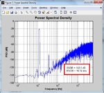
I NEED help on getting the PSD as what delsig has come out.. how do i do that out from simulink? PSD block? FFT block or specturm scope??
i need to get this out? psd output.jpg how to do it?
 
Last edited:

sorry dawson, currently m working on DSMs only. once this part is complete i will go further for decimation filter. but i want to tell u one thing. please go for SDtoolBox by malkovati. "http://www.mathworks.in/matlabcentral/fileexchange/2460-sd-toolbox" . here low-pass second order SDM demo is given.. u can compare your result from the demo's waveform, by applying different different OSR values. hope this would be help.. if u found any prob regard to this.. let me know abt that.

i have one question regard to your design.. have you done behavioral modeling of ur design ???
 

nope.. what is the proper approach to come out with a dsm simulation.. ? what is a behavioral modelling any examples?
 

behavioral modeling is a ideal approach for getting DSM design. its all about to define the behavior of ur DSM first, then go through ur DSM simulation. for example. what are the specification, and which topology u wanted to opt for designing the DSM. And the tool which i gave you, basically a simulink based tool. and u can find some gud example there. if u want to knw more abt the behavioral modelling then Richard Scherier's book "understanding of Sigma Delta Converter" is very much useful. i am also applying this strategy to full my requirement. its abt to incorporate the all non-ideal behavior of the noise at the input of DSM from this u would get a practical design of DSMs
 
  • Like
Reactions: dawson

    dawson

    Points: 2
    Helpful Answer Positive Rating
i've already gotten a copy of that book but find it rather hard to understand maybe it just me.
 

how did you got 1 bit DAC in simulink???
 

Status
Not open for further replies.

Similar threads

Part and Inventory Search

Welcome to EDABoard.com

Sponsor

Back
Top