Continue to Site

Welcome to EDAboard.com

Welcome to our site! EDAboard.com is an international Electronics Discussion Forum focused on EDA software, circuits, schematics, books, theory, papers, asic, pld, 8051, DSP, Network, RF, Analog Design, PCB, Service Manuals... and a whole lot more! To participate you need to register. Registration is free. Click here to register now.

[SOLVED] TRL calibration of a microstrip PCB fixture

Status
Not open for further replies.

snafflekid

Full Member level 4
Joined
May 9, 2007
Messages
211
Helped
31
Reputation
62
Reaction score
8
Trophy points
1,298
Location
USA
Activity points
2,644
Hello RF gurus,

I should start by saying that I am trying to make insertion loss measurements on an analog switch in the 1 to 3 GHz range.

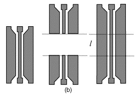
I have a PCB fixture that uses an SMA connector followed by a microstrip to connect to the pin on a soldered package. This PCB also includes two separate microstrips that I assume are used for TRL calibration. The first calibration microstrip is the length of 2 microstrips used in the fixture. I assume this is used to perform the THRU test. The second calibration strip is about half the length of the first calibration strip. Would this be used for the LINE test? I don't have the board in front of me now so I cannot say what the precise lengths of these two calibration strips are. Regarding the REFLECT test, can I connect the test port to one end of the LINE strip and leave the other end of the line strip open?

I have been reading much about the subject, but these details are eluding me.

Thank you!
 

What is most confusing is that I expect the LINE strip to be longer than the THRU strip.
 
  • Like
Reactions: bdkarl

    bdkarl

    Points: 2
    Helpful Answer Positive Rating
This PCB also includes two separate microstrips that I assume are used for TRL calibration.

Two lines only? For TRL, you should have three lines.

The first line would be the through standard, and the reference plane is at the middle of that line.
The reflect lines would be half the length of the through line.
And the delay line would be longer than the through line (extra length depends on center frequency of calibration band).

7379450800_1355735219.png


Maybe the lines that you have are for some simple de-embedding scheme.
 

The "longer" thru line may be intentional by test-board and device maker, to reduce connection loss from the device-only parameters to be measured.
SPDT or SPST switches are usually tested for insertion loss, return loss and isolation. If tested for return loss and iolation, the unused RF ports MUST be terminated in 50 OHms. Make sure your test signal generator output is allowed for the tested device. Use good RF blocking for DC and video (control) lines to prevent their effect on RF results.
 
The through and reflect are not frequency dependent, but the line does have a limited frequency range over which it can be used.

Maybe they provide one standard fixture with T and R, and then separate ones for L depending on the frequency.
 

Photo1mod.jpg

Now I have had the chance to look at the bandwidth test fixture more closely. I attached a picture.

The longer calibration standard is twice the length of one of the fixture microstrips and the shorter calibration standard is half the length of the longer standard.

Thank you jiripolivka for the advice. This analog switch is for passing LVDS signals. I don't have the luxury of having differential microstrips since this is a generic test fixture. I am in the process of renting a VNA with bias tees which should allow me to bias the switch to a voltage. I have never used a VNA with bias tees.

Maybe this board is designed for a through-reflect-match cal kit?

Through standard is the long microstrip
Reflect standard is the short microstrip with one end connected to a test port and other end open
Match standard is the short microstrip with one end connected to a test port and other end shorted with a 50 ohm SMA terminator

It is a guess, any opinons?
 
Last edited:

Okay I found out today that one of my co-workers made this board and he put these strips on the board to measure delay. It is pure coincidence that the long strip is 2x the fixture length! These were not made to be part of a calibration kit. He put these on the board to measure their propagation delay as a check to see if the board manufacturer had built the boards correctly.

We then discussed how he calibrates the board to de-embed the DUT. He said that he uses these test microstrips to measure the delay and then adds that delay to the calibration data (which, I assume, moves the reference plane from the coaxial cable ends to the DUT.) He said that because the microstrips are made 50 ohms, it is okay to do this. He said as a check I can short and open one of the microstrips on the fixture and compare it to his test microstrips.
 

Status
Not open for further replies.

Similar threads

Part and Inventory Search

Welcome to EDABoard.com

Sponsor

Back
Top