Continue to Site

Welcome to EDAboard.com

Welcome to our site! EDAboard.com is an international Electronics Discussion Forum focused on EDA software, circuits, schematics, books, theory, papers, asic, pld, 8051, DSP, Network, RF, Analog Design, PCB, Service Manuals... and a whole lot more! To participate you need to register. Registration is free. Click here to register now.

130 GHz BPF: Difference in measured and simulated results

Status
Not open for further replies.

Torie

Newbie level 4
Joined
Jun 18, 2012
Messages
6
Helped
0
Reputation
0
Reaction score
0
Trophy points
1,281
Location
Fort Collins, CO
Activity points
1,328
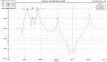
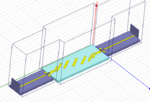
Hi, I am currently working on a design of a 10% BPF at 130 GHz. I used Ansoft HFSS to do the initial simulations and got very good predicted performance. However, when I measured it, the lower side of the band had an extremely slow roll off. I have gone back to my simulation and added in the wire bonds and the testing structure and I was able to account for a few differences; however, I can't seem to track down the reason why the filter had such a poor performance on the lower end of the pass band. Any suggestions would help! Some sources of error I have already investigated are: tolerances, testing structure, lower conductivity gold, and wire bonding.

<a title="Simulated_Performance.jpg" href="http://obrazki.elektroda.pl/5687909900_1354824668.jpg"><img src="http://obrazki.elektroda.pl/5687909900_1354824668_thumb.jpg" alt="Simulated_Performance.jpg" /></a><a title="Simulation_Pic.png" href="http://obrazki.elektroda.pl/4978662000_1354824669.png"><img src="http://obrazki.elektroda.pl/4978662000_1354824669_thumb.jpg" alt="Simulation_Pic.png" /></a><a title="Performance_Comparison.png" href="http://obrazki.elektroda.pl/3530906600_1354824670.png"><img src="http://obrazki.elektroda.pl/3530906600_1354824670_thumb.jpg" alt="Performance_Comparison.png" /></a>
 

Attachments

  • Performance_Comparison.png
    Performance_Comparison.png
    45.2 KB · Views: 173
  • Simulated_Performance.jpg
    Simulated_Performance.jpg
    111.4 KB · Views: 183
  • Simulation_Pic.png
    Simulation_Pic.png
    201.7 KB · Views: 146
Last edited:

At 130 GHz, 2.3 mm wavelength, problems like you describe are quite common. The substrate can be inhomogeneous and metal thickness, too. Wire bonds are highly problematic at such high frequency.
Technically better is to combine a high-pass and a low-pass filter for the best response.
 
By low pass filter, do you mean to design band stop filters? Is there anything I can do to combat this behavior?
 

I think you can find many papers on a similar subject. Mostly at lower frequencies but similar problems. You can design a low-pass filter with generally known concept as well as the high-pass. BOth are made in waveguide and their response can easily be "tuned". Tuning your stripline filter is also possible, so try it.
 
  • Like
Reactions: Torie

    Torie

    Points: 2
    Helpful Answer Positive Rating
It looks like the filter is somehow bypassed in the real design. Either discontinuous ground connection or coupling "over-the-air" by waveguide effects are the favourite candidates, I think.
 
  • Like
Reactions: Torie

    Torie

    Points: 2
    Helpful Answer Positive Rating
There are two things going on in your design.
1. As you already mentioned correctly, the bondwire transition degrades the performance of the filter badly. You can see this in the simulated return loss of the filter. I assume the return loss caused by this transition is around 10dB, but you have two of them. In order to get better performance you should optimize the transition first as a stand-alone component. This is not so hard, it is likely that the bondwire will behave like a series inductor, which can be cancelled in first order with a parallel capacitor (or stub) before of after the board.
2. The bandwidth of the measured filter is quite much larger than the simulation. You can see this because the S11 return loss fluctuates around 10dB for frequencies far below the lower cutoff frequency. This means that there is something wrong with the coupling values. The bandwidth is too high, which means the resonators should be separated further. Also you'll see that the center frequency will have to be shifted to a higher frequency so the resonators should be made a little shorter.

I think you should tackle these problems separately. You can consider using TRL calibration in the filter substrate in order to deembed the transitions and only measure the filter performance. And you can just add a plain 50 ohm line connection instead of the filter to test the performance of the transition.

At these frequencies, the issues you encounter are normal. It is practically impossible to model all aspects of the design perfectly. So you just go ahead and breadboard a few iterations until you get there.
 
Thank you all so much for your responses, I appreciate the feedback. Ideally, I would have liked to put vias directly on the filter so I didn't have to deal with the bond wires etc. however, I cannot due this due to the tolerances of the company manufacturing the BPF. I will take your suggestions and see if I can correct this problem. Ideally, I would like to be able to simulate the cause of the large bandwidth and then correct it from there but it seems as if that might not be possible. Once again, thank you for all your responses.
 

You didn't describe how you've measured the filter. A photo of the measurement setup might also give some clues...
 

Status
Not open for further replies.

Part and Inventory Search

Welcome to EDABoard.com

Sponsor

Back
Top