Continue to Site

Welcome to EDAboard.com

Welcome to our site! EDAboard.com is an international Electronics Discussion Forum focused on EDA software, circuits, schematics, books, theory, papers, asic, pld, 8051, DSP, Network, RF, Analog Design, PCB, Service Manuals... and a whole lot more! To participate you need to register. Registration is free. Click here to register now.

Floquet's ports in CST

Status
Not open for further replies.
It will be an interesting comparison between the two grounds plane at a same time.
Will simulate and generate the phase curves and then it will be easier to compare without ground, ground at z=0 and
ground at z=0.1 lambda.

but i'm still not sure if most paper/papers consider the effect of ground then why in this paper it's without taking it into consideration.
 

You don't have to simulate it. The results are obvious. The case with "only front ground plane", and "two ground planes" will be same. If you simulate "only second ground plane" to subtract it's effect on your reflection you will get wrong results, because in two ground plane case, your second ground plane has absolutely no effect in reality.

I'm just giving you that example to show you that ground plane subtraction may not have any meaning except for certain cases where you want to see how it compares with a plain ground plane.

Can you give me one of those references which makes this subtraction?
 

You are right, I confirmed it and the results are same.

Take any paper of single layer reflectarray and after simulating you will find out that the phase plots
are achieved after subtracting the ground effects.

Do you have any knowledge about FSS ?
 

I do. I haven't done reflectarrays but I have developed a finite element rigorous coupled wave method for periodic structures. In fact I'm doing a sort of polarization selective surface design.
I checked couple papers (I cannot check all of them, just on ieee, there are about 165 journals) but I didn't come across with that kind of comparison. If you send me one of them, I may read and try to see their reasoning.
 
@Chameleon

Hey,

Sorry for the late reply. I was away. You find some paer related to that or you still want me to provide you with it?

These days i'm simulating a frequency selective surface for which i'm trying to assign PML in HFSS. Would you like to suggest me
something regarding that?

Thanks'
Arslan.
 

Aoa, I ll be thankful if u answer 2 of my questions.
1) How to assign a floqet port?
2) what are the boundry conditions for this?

- - - Updated - - -

Aoa, I ll be thankful if u answer 2 of my questions.
1) How to assign a floqet port?
2) what are the boundry conditions for this?

- - - Updated - - -

I ve 2 quesions regarding this topic..
1) How to assign floqet port?
2) How can we obtain reflectivity graph in the results??
 

Hey,

If you are using CST MWS then choose FSS unit cell from the template and then design the required structure.
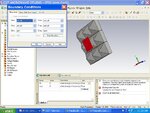
For boundary conditions choose unit cell boundaries, it will assign Floquet's port on each side of the structure.
Reflectivity you can see form the s11 curve.
 
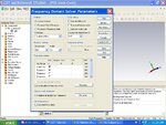
182323_432970256758785_1531949845_n.jpg Please check the above image and guide me how can i rectify this problem...?

- - - Updated - - -

- - - Updated - - -

182323_432970256758785_1531949845_n.jpg These are my settings for FD Solver..
 

Status
Not open for further replies.

Part and Inventory Search

Welcome to EDABoard.com

Sponsor

Back
Top