Continue to Site

Welcome to EDAboard.com

Welcome to our site! EDAboard.com is an international Electronics Discussion Forum focused on EDA software, circuits, schematics, books, theory, papers, asic, pld, 8051, DSP, Network, RF, Analog Design, PCB, Service Manuals... and a whole lot more! To participate you need to register. Registration is free. Click here to register now.

[SOLVED] PIC Assembly: variable delay routine

Status
Not open for further replies.

T3STY

Full Member level 4
Joined
Apr 17, 2012
Messages
239
Helped
24
Reputation
48
Reaction score
24
Trophy points
1,308
Activity points
3,715
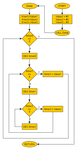
I'm experimenting with assembly delays and I have come across a workflow model that can uses 3 8-bit registers for delaying up to 16581375 cycles (without considering the instructions delay). You can find the diagram in the attachment. I've then implemented the model in assembly and works fine except for 1 problem: it's 4 times slower than it should. I have also calculated that if I have a 4MHz PIC clock the real clock is 1MHz, so there are 1milion instructions in a second. By using the model before I can make timers do 250*250*16 loops which makes exactly 1000000 loops so 1 second delay. Although, when I run the code in ISIS it makes a 4 seconds delay (left out the error caused by not considering the delay of the instructions themselves).
Code:
#DEFINE T0 0xFA	;250
#DEFINE T1 0xFA	;250
#DEFINE T2 0x40	; 16
Delay
	CBLOCK 0x0C
		TIMER_0: 1
		TIMER_1: 1
		TIMER_2: 1
	ENDC
	
	MOVLW T0
	MOVWF TIMER_0
	MOVLW T1
	MOVWF TIMER_1
	MOVLW T2
	MOVWF TIMER_2
	
	loop_t0			; 1ST loop
		DECFSZ TIMER_0,f;
		GOTO loop_t1	; while not 0:	go to loop_t1
	RETURN			; else:			the delay has finished, return from call
		
	loop_t1
		DECFSZ TIMER_1,f; 2ND loop
		GOTO loop_t2	; while not 0:	go to loop_t2
	
	MOVLW T1		; else:			restore value into TIMER_1
	MOVWF TIMER_1		; 			needed for any further loop
	GOTO loop_t0		; 				then go to loop_t0
		
	loop_t2			; 3RD loop
		DECFSZ TIMER_2,f;
		GOTO loop_t2	; while not 0:	DEC TIMER_2
	
	MOVLW T2		; else:			restore value into TIMER_2
	MOVWF TIMER_2		; 			needed for any further loop
	
	GOTO loop_t1		;				then go to loop_t1
END
I know this delay routine is still not perfect because it does not consider situations where timer0 is 0 and the others will not be executed at all, that's an issue I'm going to deal with when using it. But the problem here seems to be calculus, somehow...
Can someone tell me if I miscalculated the loops? Or did I wrongly consider the 1MHz real clock?

p.s. Running on a 16MHz PIC clock I get the 1 second delay and changing values also gives me the required delay.
 

Attachments

  • delay.png
    delay.png
    16.7 KB · Views: 145

I'm not sure why the delay isn't working but there is a cycle accurate delay routine on Microchip's own forum if you search for it.

Are you taking into account that 'goto' is a two cycle instruction and 'decfsz' can be either one or two cycles depending on the result?

Brian.
 

As I said before I didn't take into account the delay every instruction takes, only the decrement instruction is considered as 1 loop. It doesn't give accurate result but there would be about 10 loops error, not that much to give a 4 times longer loop.
I'll be looking for the routine you mentioned but I'd be glad to understand where the mistake is in my code.
 

Hi,

You are correct in the Fosc/4 = 1 machine cycle, however not all instructions take 1 cycle, some like Goto and Decf can take 2 or even 3 cycles depending on the chip used.

If you see the Assembly instruction section of the datasheet it shows how many cycles each one takes.

While you have the idea of how a software delay loop works, calculating one yourself can be a chore.
I cheat and use this calculator, though always check the complete code in Mplab Sims Stopwatch

**broken link removed**

Also avoid using register names like Timer_1 as it will be too easy to mix up with the system Timers 0 ,1 2 etc.
 

You first post says ... without considering the instructions delay ... But if you want a delay routine, that is the only thing you have to consider! You have to add up the number of instruction cycles for each instruction, being careful of any that can take different variable amounts.

Keith
 

Sorry for late reply, I've been busy.

I found the error in my code, it is the GOTO instruction wich is 2 cycles. So the equation my code describes, instead of TIMER_0 * TIMER_1 * TIMER_2 is (2*TIMER_0) * (2*TIMER_1) * (2*TIMER_2).

Thanks for the heads up wp100, although I had already found the code a few days ago ;)
 
I'm coming back to this thread because I'm (again) missing something. Microchip's 32 bit delay routine (link above) is not working by simply copy-pasting it, neither by changing some register addresses. I've decided again to write my own code, and I've came out with this:

Code ASM - [expand]
1
2
3
4
5
6
7
8
9
10
11
12
13
14
15
16
17
18
19
20
21
22
23
24
25
26
27
28
29
30
31
32
33
34
35
36
37
38
39
40
41
42
43
44
45
46
47
48
49
50
51
52
53
54
55
56
57
58
59
60
61
62
63
64
65
PROCESSOR       16F84A
RADIX           DEC
INCLUDE         "P16F84A.INC"
__CONFIG        0x3FF1
 
ORG 0x0C
TIMER_0         RES 1
TIMER_1         RES 1
TIMER_2         RES 1
TIMER_3         RES 1
 
ORG 0x00
BANKSEL         TRISA
CLRF            TRISA
BANKSEL         PORTA
 
GOTO main
 
Delay MACRO nCK         ; TOT: 8 + 4 + 16*nCK
        MOVLW   nCK & 0xFF                                      ; 1
        MOVWF   TIMER_0                                         ; 1
        MOVLW   (nCK >> 0x0000FF) & 0xFF        ; 1
        MOVWF   TIMER_1                                         ; 1
        MOVLW   (nCK >> 0x00FFFF) & 0xFF        ; 1
        MOVWF   TIMER_2                                         ; 1
        MOVLW   (nCK >> 0xFFFFFF) & 0xFF        ; 1
        MOVWF   TIMER_3                                         ; 1
        
        CALL    f_delay         ; TOT: 4 + 16*nCK
ENDM
 
main
        BSF             PORTA, 0
        Delay   62499
        BCF             PORTA, 0
        Delay   62499
GOTO main
 
f_delay
        MOVLW   0x01            ; 1
        SUBWF   TIMER_0, f      ; 1
        
        BTFSC   STATUS,  C      ; 1
        SUBWF   TIMER_1, f      ; 1
        
        BTFSC   STATUS,  C      ; 1
        SUBWF   TIMER_2, f      ; 1
        
        BTFSC   STATUS,  C      ; 1
        SUBWF   TIMER_3, f      ; 1
        
        CLRW                            ; 1
        
        IORWF   TIMER_0, W      ; 1
        IORWF   TIMER_1, W      ; 1
        IORWF   TIMER_2, W      ; 1
        IORWF   TIMER_3, W      ; 1
        
        BTFSS   STATUS,  Z      ; 1
        GOTO    f_delay         ; 2
        
        NOP                                     ; 1
RETURN                                  ; 2
 
END


If my calculations are right the f_delay subroutine should take 16 clocks per delay + 4 clocks (2 call, 2 return), and the Delay macro should take 8 more clocks (follow comments for clock counts). With the value 62499 it should take about 1 second delay each time the macro is used (16*62499+12=999996 CK).
Now, even if I'm right or wrong, the code above should make some delay. I've tried compiling it but then I've received these messages from MPLAB:
Code:
----------------------------------------------------------------------
Release build of project `C:\Users\T3STY\Documents\MPLAB\ASMTest\ASMTest.mcp' started.
Language tool versions: MPASMWIN.exe v5.44, mplink.exe v4.42, mplib.exe v4.42
Sat Dec 15 18:53:01 2012
----------------------------------------------------------------------
Make: The target "C:\Users\T3STY\Documents\MPLAB\ASMTest\main.o" is out of date.
Executing: "C:\Program Files (x86)\Microchip\MPASM Suite\MPASMWIN.exe" /q /p16F84A "main.asm" /l"main.lst" /e"main.err"
Warning[205] C:\USERS\T3STY\DOCUMENTS\MPLAB\ASMTEST\MAIN.ASM 1 : Found directive in column 1. (PROCESSOR)
Warning[205] C:\USERS\T3STY\DOCUMENTS\MPLAB\ASMTEST\MAIN.ASM 2 : Found directive in column 1. (RADIX)
Warning[205] C:\USERS\T3STY\DOCUMENTS\MPLAB\ASMTEST\MAIN.ASM 3 : Found directive in column 1. (INCLUDE)
Warning[205] C:\USERS\T3STY\DOCUMENTS\MPLAB\ASMTEST\MAIN.ASM 4 : Found directive in column 1. (__CONFIG)
Warning[205] C:\USERS\T3STY\DOCUMENTS\MPLAB\ASMTEST\MAIN.ASM 6 : Found directive in column 1. (ORG)
Warning[205] C:\USERS\T3STY\DOCUMENTS\MPLAB\ASMTEST\MAIN.ASM 12 : Found directive in column 1. (ORG)
Warning[205] C:\USERS\T3STY\DOCUMENTS\MPLAB\ASMTEST\MAIN.ASM 13 : Found directive in column 1. (BANKSEL)
Warning[203] C:\USERS\T3STY\DOCUMENTS\MPLAB\ASMTEST\MAIN.ASM 14 : Found opcode in column 1. (CLRF)
Message[302] C:\USERS\T3STY\DOCUMENTS\MPLAB\ASMTEST\MAIN.ASM 14 : Register in operand not in bank 0.  Ensure that bank bits are correct.
Warning[205] C:\USERS\T3STY\DOCUMENTS\MPLAB\ASMTEST\MAIN.ASM 15 : Found directive in column 1. (BANKSEL)
Warning[203] C:\USERS\T3STY\DOCUMENTS\MPLAB\ASMTEST\MAIN.ASM 17 : Found opcode in column 1. (GOTO)
Warning[205] C:\USERS\T3STY\DOCUMENTS\MPLAB\ASMTEST\MAIN.ASM 30 : Found directive in column 1. (ENDM)
Error[118]   C:\USERS\T3STY\DOCUMENTS\MPLAB\ASMTEST\MAIN.ASM 27 : Overwriting previous address contents (000C)
Error[118]   C:\USERS\T3STY\DOCUMENTS\MPLAB\ASMTEST\MAIN.ASM 29 : Overwriting previous address contents (000D)
Error[118]   C:\USERS\T3STY\DOCUMENTS\MPLAB\ASMTEST\MAIN.ASM 35 : Overwriting previous address contents (000E)
Error[118]   C:\USERS\T3STY\DOCUMENTS\MPLAB\ASMTEST\MAIN.ASM 20 : Overwriting previous address contents (000F)
Warning[203] C:\USERS\T3STY\DOCUMENTS\MPLAB\ASMTEST\MAIN.ASM 37 : Found opcode in column 1. (GOTO)
Warning[203] C:\USERS\T3STY\DOCUMENTS\MPLAB\ASMTEST\MAIN.ASM 63 : Found opcode in column 1. (RETURN)
Warning[205] C:\USERS\T3STY\DOCUMENTS\MPLAB\ASMTEST\MAIN.ASM 65 : Found directive in column 1. (END)
Halting build on first failure as requested.
----------------------------------------------------------------------
Release build of project `C:\Users\T3STY\Documents\MPLAB\ASMTest\ASMTest.mcp' failed.
Language tool versions: MPASMWIN.exe v5.44, mplink.exe v4.42, mplib.exe v4.42
Sat Dec 15 18:53:02 2012
----------------------------------------------------------------------
BUILD FAILED
I really can't understand those errors because they seem to be totally random. Each line indicated in the error messages has nothing to do with the others. Also, why would I be 'overwriting previous address contents' ?? And even if I am overwriting contents, why do you (the compiler) complain about it?
 

Hi,

You have loads of rather obvious warnings and errors there, you should be able to correct most of them.

If you click on a line in the error message it takes you straight to the line in your actual code.

Have quickly corrected those error so its builds ok, the main problem is the ORG you used to specify the variables. - use Cblock .

Have not got time at the moment to go though your logic, but you can use MPlabs simulator and stop watch to check your work.
 

Attachments

  • delay.rar
    518 bytes · Views: 110
  • Like
Reactions: T3STY

    T3STY

    Points: 2
    Helpful Answer Positive Rating
Hi,

Tried to Simulate your code but it would not return any delay, just going though each line of code .

Rather than try seeing where your error is I have done a simpler macro based delay for you to try and work out from, think you can see it a lot easier routine.

Also did a 3 argument macro for you to try - again works fine

Always check your timing with MPlabs Stopwatch as the pic shows, ISIS does not always run in real time for many reasons.
 

Attachments

  • macro_delay.rar
    63.1 KB · Views: 136
  • Like
Reactions: T3STY

    T3STY

    Points: 2
    Helpful Answer Positive Rating
I understood the mistake I was doing before with ORG 0x0C, thanks!
Also, about your routine, what a nice work! It works great! Only tell me one thing: the PIC registers are 8-bit and can be used to store integers. How are you able to store decimal numbers?
 

Hi,

You specify whatever radix you want, binary ,decimal, hex, octal ,ascii, it all gets stored in a 8 bit register in binary form, the assembler does all the work for you.

There is alway a project default for the radix, you have specified decimal in your code so any value will be taken as decimal, unless you specify differently such as 0x04 or H'04' or b'00000100' etc

I tend to use a radix of hex , so thats why I set the delay arguments to .100 meaning decimal 100, though not really needed with the radix set to decimal
 

Attachments

  • ScreenShot001.jpg
    ScreenShot001.jpg
    162.3 KB · Views: 137

oh ok, got it. the dot_number doesn't mean "0.1" but "1 decimal". I have misinterpreted that with floating point numbers :)
 

Hi,

Yup , you have got it, though an easy mistake to make.
 

Status
Not open for further replies.

Similar threads

Part and Inventory Search

Welcome to EDABoard.com

Sponsor

Back
Top