Continue to Site

Welcome to EDAboard.com

Welcome to our site! EDAboard.com is an international Electronics Discussion Forum focused on EDA software, circuits, schematics, books, theory, papers, asic, pld, 8051, DSP, Network, RF, Analog Design, PCB, Service Manuals... and a whole lot more! To participate you need to register. Registration is free. Click here to register now.

Can anybody explain the following opamp circuit working

Status
Not open for further replies.

k.kumar1044

Newbie level 3
Joined
Jul 10, 2012
Messages
4
Helped
0
Reputation
0
Reaction score
0
Trophy points
1,281
Activity points
1,314
Hello ,

Can anybody explain the section wise working of the following opamp circuits.
Specially the capaitance resistance pairs in the begning.
Plz help .

thanking you all in advance.
 

Attachments

  • K (2).jpg
    K (2).jpg
    214 KB · Views: 115
Last edited:

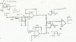
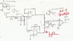
Referred to the input of the last opamp (without any feedback) the circuit works as an allpass.
This means that for different frequencies the amplitudes remain constant and the phase is shifted as a function of frequency.
This description does not yet include the function of the input bandpass which can be described separately.
 
plz tell me what those capacitance and resitance pair at the start doing.. Is it band pass filter? Thanks
 

its a band pass filter.....with series RC acting as a HIGH PASS and parallel RC acting as LOW PASS....

EA
 
any guess , whats happening in this section .. in terms of addition of current and voltages of different phases..anything will be helpful

Thanks
 

Attachments

  • K (2).jpg
    K (2).jpg
    179.7 KB · Views: 79

any guess , whats happening in this section .. in terms of addition of current and voltages of different phases..anything will be helpful
Thanks

`"What's happening in this section" ?

This section summarizes two signals: Vout1+Vout2.

Vout1=Vin*[1/(1+jwRC)] >> first-order lowpass
Vout2=-Vin*[jwRC/(1+jwRC)] >> first order highpass.

To proove that the magnitude of the sum is constant and the phase moves from zero to -180deg. you must evaluate the sum of both output signals separately as magnitude and phase.
The calculation is rather straight forward - however a bit involved.

- - - Updated - - -

Why do you expect a triangle shape at the output?
 
Status
Not open for further replies.

Part and Inventory Search

Welcome to EDABoard.com

Sponsor

Back
Top