Continue to Site

Welcome to EDAboard.com

Welcome to our site! EDAboard.com is an international Electronics Discussion Forum focused on EDA software, circuits, schematics, books, theory, papers, asic, pld, 8051, DSP, Network, RF, Analog Design, PCB, Service Manuals... and a whole lot more! To participate you need to register. Registration is free. Click here to register now.

Electronic circuit that will make two consecutive switches when it's turned on.

Status
Not open for further replies.
of corse,
relley2.2.JPG
using the time delay relley RTA100S, when powered on the relley waits the pre-seted time and then clamps (see for other types available near to your place).Microcontroller is a good option if you have time to spend for it... (you need to build a circuit & you need a programmer)
 
Last edited:
@aleks
I made one proto with 89c2051 microcontroller. See if you can use it. You may require Proteus simulation software to see its working...
Obviously this circuit is not checked, but it will work.
 

Attachments

  • Remote.rar
    81.4 KB · Views: 49
@aleks
I made one proto with 89c2051 microcontroller. See if you can use it. You may require Proteus simulation software to see its working...
Obviously this circuit is not checked, but it will work.

Genovator,

Thank you very much, i appreciate this, however after googleing a little bit i see that i have to have a pretty good knowledge in micro controllers, programming etc in order to build this and i don't know if it's a good idea to invest in something like that just for this particular situation. I hope that someone else will find your solution useful. I have no doubt that is working but it's a new field for me.

This is what i managed to achieve:
Using only two pins from one dc relay, i managed to turn on the AC after a power outage but the problem is that after that i have to put the remote control in the OFF state manually until the next power failure.
I've been experimenting with two relays but i didn't had any success.

This is what i did.
I extracted two wires from the on/off button
Untitled.jpg

I wanted to use the third pin from the relay in order to turn off the remote when the power is gone but i didn't had any success.
I thought that the transit time of the middle (moving) contact would be equal of a person releasing the ON/OFF button and when it gets to the third contact it would equal a person pressing on the ON/OFF button again in which case i would have achieved my goal. But no luck :( I don't know if i am missing something really simple.
Here is the same image, when i used the third pin.

Untitled.jpg

If you guys have something else for me to try, i would really appreciate it.

Anyway, thanks for everything that you have done!

All the best,

Aleks
 
Last edited:

hi,
u confuse me with the expression "I managed to turn on the AC" . Do you mean you managed to turn on the air conditioner ? if so after that you need to do what?
are we talking about a IR remote controller (like at the TV's) ?

PS : try better this
airgap.jpg
(as my sugestion in previous posts, you need only 1 pulse vhen ac comes beck)
 
Last edited:
@zsolt1

Yes, i meant that i managed to turn on the Air Conditioner and yes i am talking about an IR remote controller.
I am not planing to make any kind of modification to the air conditioner itself. Just the remote controller.

The problem with the 1 pulse is that it will just send an OFF signal to the air conditioner and the air conditioner will receive that OFF signal and it will not turn on (because before the power outage the remote controller is in ON mode where you can set temperature and stuff like that). As i said before, i can use that one pulse, but after every power outage i will have to manually put the remote controller in OFF state so on the next power outage, when the power comes back, it will send ON signal to the air conditioner. Which is a partial solution since its not fully automatic. Have in mind that the remote controller has its own power supply (batteries) and it's not influenced by the power outage.
So speaking of this, if i have 2 pulses, separated by 0.5 second or 1 second, on the first pulse, it will send an OFF signal to the air conditioner, which will eventually do nothing, and then on the second pulse it will send the ON signal which eventually will turn on the air conditioner.

I hope i explained it right.

If i understood you correctly, your schematic will make the DC relay click and then it will get back in the previous state, right?

Thanks,

Aleks
 

yes, after each pover outage , when the power comes beck the relley will click once . Do you need an other click after that ? Do you need 2 consecutive clicks when the power comes beck with a short delay betven them ?
 

ok, take a lok at this
**broken link removed**
airgap2.jpg
it should work like this: after outage when power comes beck, REL1 & REL3 clamp once. REL1 gives the first pulse to the remote, and REL3 gives one pulse to REL2 (which clamps immediatley) and the 1000uF capacitor. The 1000uF capacitor continues to suply REL2 a little lime (the desired delay time, so to increase it you increase the cap's value). After REL2 comes beck to initial state, it introduces beck in the circuit the 2 x C (valued ) capacitor (which was shorted for the deleyed time -discharged-), so REL 1 will clamp one more time .
This scenario should repeat itself every outage . The only disadvantage is that you need 3 relleys. There are other solutions to, for shore.... (for example something built around the concept that 'a diode is blocked in reverse polarization by a charged capacitor which discharges on a rezistor ......... ' ) (or Genovator's fancy microcontrolered solution ...)
 
Last edited:
zsol1 Thank you a thousand times!!! I owe you a beer or two :))

One last question, how about two circuits, identical to your previous schematic (the one with one click), but with different values for the capacitors, which will cause delayed click on the second circuit?
What is your opinion?

Thanks again!
 

hi,
take it easy with the beer since it may not work, it's just in theory, practice will decide ... hehe .. so i sugest to test it
at the previous circuit, the single pulse comes imediatley when power is beck. If you increase the capacitor value you increase the time that the relley stays clamped.
PS: about the power suply you are using, i think it gives maximum 5 V , since it's a cel phone charger . That means your 12Vdc relleys will never clamp , so you have to use 5V relleys . If it can deliver 12V it is ok , 12 V relleys are good.
best regards,
Z1
;-)
 
Last edited:

Using only two pins from one dc relay, i managed to turn on the AC after a power outage but the problem is that after that i have to put the remote control in the OFF state manually until the next power failure.

Yes, this is why I choose a uC. Anyway, use any circuit convenient to you, as you are not familiar with uC's, it would be difficult for you to use it. I was trying to simulate zsolt's circuit. Maybe I am making some mistake.


I don't know why the relays are always left on. May be I missed something. I need zsolt to check whether I made the designed correctly....
 

hi,
I am not familiar with simulator programs but i would point to the foloving issues about your simulation:
- the design is corect , but from the picture you captured i can't take out if contact positions are in clamped or unclamped state of relleys... anyway in my drawing i represented al contact positions in unclamped state (steady state) of relleys , so could you check this aspect ?
- the supply of the circuit. I see in the picture the simbol for pulsatory dc current. If so that is not ok. Inded it is not ac (it does not pass thru 0) but it is still variable in time, which mens that it produces conduction by polarization in capacitors dielectric so relleys are clamped . Could you serch your programs library for a dc supply (simply battery will do) ? (or filter with 1000uF cap the pulsatory dc you are using now )
obs.
in continuous dc , curent does not pass tru condensator since the condensators dielectric isolates the armatures. When aplying variable voltage (pulsatory or ac) , current passes thru capacitor by "conduction by polarisation " (electric dipoles of the dielectric align up and folow electric field ..... long story to be typed here ).
Even when operateing in dc, when applying the supply to the circuit, lets say 12 V, the voltage on the condensator rises from 0 V to the applied voltage level of 12 V . The time period in which the voltage on the cap rises from 0 to 12 v its' called a transitory moment, and gues what ? in that period of time we can say that voltage is variable, so for that period curent pases tru capacitor .... ( i don't want to bore you with electrotehnic ...)
tranzitory cap.JPG


Thanks for testing in simulator program, could you re do the simulation regarding the above aspects ?
PS : increse the simulations time seting to ~5 sec , so that you can catch both clamps
 
Last edited:

Hi aleks2x,
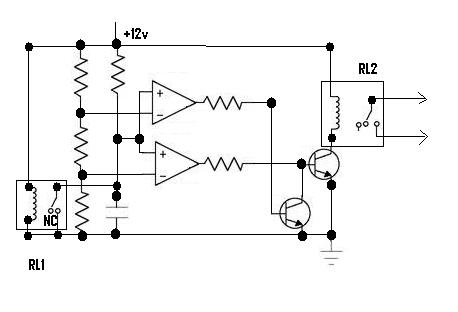
This circuit is made for you it will make a click (RL2)some time after the power resumes and fall back Ic can be LM324, Transistors BC548 Resistors 10k, capacitor according to delay.If it helped you click the helped button below
7_1347548894.jpg

regards ani
 

Dear zsolt...
from the picture you captured i can't take out if contact positions are in clamped or unclamped state of relleys...
Its all in unclamped state as yours.

the supply of the circuit. I see in the picture the simbol for pulsatory dc current.
The supply is constant DC 5V, its not pulse voltage.
 

Dear zsolt...

Its all in unclamped state as yours.


The supply is constant DC 5V, its not pulse voltage.

the simbol : interupted line above continuous line is not dc, it is pulsatory dc , or simply "unfiltred dc " (not that dc you have from battery )
 

Its not pulse. Its DC. I use proteus and I know about it. Its a constant supply of 5V.
 

Its not pulse. Its DC. I use proteus and I know about it. Its a constant supply of 5V.

aha... is the program called proteus ? where can i get it ?
it stil would be nice if someone that has those fancy simulators could test the circuit without that nasty simbol ... (it bothers my fantasy :smile: )

Ps: the circuit presented in post #24 works , i used a 5 V dc reley (miniature) and 1000uF/16 V cap (i did not use cell phone charger because i have dc power supply),
i could not test the last circuit with 3 releys since i have only 1 , i think it stil may work
 
Last edited:

You can get it from **broken link removed**.

- - - Updated - - -

You can get it from **broken link removed**.
 

Status
Not open for further replies.

Similar threads

Part and Inventory Search

Welcome to EDABoard.com

Sponsor

Back
Top