zmkm1302022
Junior Member level 1
i cannot understand what is the characteristic impedance of a transformer used for, is it just for finding the leakage inductance and magnetizing inductance at different frequencies??
Follow along with the video below to see how to install our site as a web app on your home screen.
Note: This feature may not be available in some browsers.
Can you provide some additional information?
my Prof. ask me to measure the characteristic impedance of toroid coil at 100KHz, he said i can adjust the turn ratio to match the impedance between the load and the signals generator. but i know the impedance of signals generator is 50 ohm, the turn ratio is easy to test as 1.3:1. so i can connect a load as 50/(1.3^2) to match the impedance. why i need to care about the characteristic impedance at 100KHz. by the way, the transformer is used to measure current signals from 1kHz to 5MHz, he said 100KHz is in the middle of 1KHz TO 10MHz, but i still dont understand how this characteristic impedance can be used to design something or what???
I would ask in a first place: what is transformer characteristic impedance? Obviously it's neither leakage nor magnetizing impedance. I wonder which quantity you gonna measure?
IMHO, the term characteristic impedance can be used for the nominal impedance of connected circuit, in other words it would be defined by the ratio of nominal transformer voltage and current. For some application fields, e.g. audio or RF, (characteristic) impedance specifications are quite common. But it's no property that can be measured directly.
If you can refer to other plausible definition of characteristic impedance, please report.
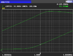
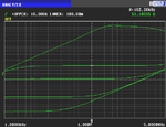
I can try to imagine a reasoning behind the said definition of characteristic impedance, but I'm not aware of it as commonly used technical term. There are stronger candidates, as mentioned by WimRFP and me.then i can find the corresponding leakage impedance Ls and magnetizing impedance Lm at 100KHz, as well as the characteristic impedance Zc=sqrt(ZLs*ZLm).
What value did you get for the characteristic impedance?
Did you consider what I posted: "But, would the transformer work as well to match 5 ohms to 2.959 ohms; .5 ohms to .2959 ohms; 500 ohms to 295.9 ohms; 5000 ohms to 2959 ohms, etc.? An ideal transformer would be able to match any of those pairs of impedances, but a real transformer would work best at some impedance level. How would you determine the impedance level for best performance?"
Hi FvM,I can try to imagine a reasoning behind the said definition of characteristic impedance, but I'm not aware of it as commonly used technical term. There are stronger candidates, as mentioned by WimRFP and me.
Unfortunately, you have been just asking for the use of the characteristic impedance definition. I fear we can't answer it for the present one.
Hi The Electrician,
do you mean we need the transformer working at a specific frequency when the characteristic impedance at this frequency is at the lowest level?
I mean that the characteristic impedance of the transformer's windings should match the impedance levels of the generator and load for lowest losses at whatever the frequency of operation is.
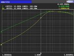
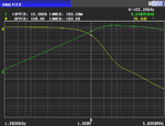
The value as in your calculation is increasing with frequency. Thus I don't think that the quantity is of much use in a wideband transformer application.I am not pursuing the definition of characteristic impedance of transformer, but i would like to know how it is used in practice to determine something. for example, can it be used to determine the pass-band of a transformer? this is just my guess.
This would be also my suggestion. Measure the well defined Ls and Lm values, they should be fairly frequency independent, and calculate all derived properties, e.g. lower and upper frequency limits of transformer usability based on your source and load impedance.maybe i dont have to concern too much about this characteristic impedance.