Continue to Site

Welcome to EDAboard.com

Welcome to our site! EDAboard.com is an international Electronics Discussion Forum focused on EDA software, circuits, schematics, books, theory, papers, asic, pld, 8051, DSP, Network, RF, Analog Design, PCB, Service Manuals... and a whole lot more! To participate you need to register. Registration is free. Click here to register now.

simple Solar inverter for home

Status
Not open for further replies.

Gvbhati

Newbie level 3
Joined
Aug 29, 2012
Messages
3
Helped
0
Reputation
0
Reaction score
0
Trophy points
1,281
Activity points
1,307
hi
I want make aninverter for my home of 1kw which converter 60 dv v to 230 ac
 

@Gvbhati

Can have a look of inverters that are available in the market including the one you want to build....
 

@Gvbhati

Can have a look of inverters that are available in the market including the one you want to build....

It not for just use in home I am also want to learn in detail about it
 

Maybe this can help you in thinking.

H-Bridge multilevel principe :
 

Attachments

  • 1328052979319-uploadscreenshot-dot-com.png
    1328052979319-uploadscreenshot-dot-com.png
    287.7 KB · Views: 108
  • an9611 DC-AC Isolated Battery Inverter.pdf
    335 KB · Views: 242
  • MQP_D_1_2.pdf
    5.3 MB · Views: 267
  • PWM_Techniques_final.pdf
    3.7 MB · Views: 283
Hi Jeffrey,

Regarding the inverter design is it possible to construct it using transistors only as it is very difficult to do it using thristor(SCR) or MOSFET because of the complexity of the Gate/drive circuit.
 

POSSIBLE BUT maintaining a stable op at higher powers is hard in trannies

we go for thyristors cos' of their reliablities in higher power appliances in real world
 
You should probably begin with your power quality requirements.
Things like lamps can be fine with square wave (simplest), some
fancier equipment and some motors really don't like fast edges
(that's why there are "inverter duty" motors that cost more).

A telcom 48V input inverter might have enough design margin
to tolerate 60V input, and be had at surplus. Maybe you want
to configure your panel farm to put out a more standard
voltage so you can take advantage of secondary-market
equipment.

why we need a oscillator, for 50hz which one is good.
to get pure sine wave LC filter is enfough
 

lc filter is not sufficient to get the exact thing which we need as they are called diminishing sinusoid generators with out intermediate excitation

so if you are considering a LC discharging ckt as a soln you are in err as it does not provide stable sine wave for longer than a few sec based on the L & C value so it is better to go with a oscillator to get a much purer and stabler sine wave
 
  • Like
Reactions: tpetar

    tpetar

    Points: 2
    Helpful Answer Positive Rating
hi
I want make aninverter for my home of 1kw which converter 60 dv v to 230 ac
Hi,
you will require 60 to 325v dc-dc converter and an H bridge driven with sine PWM to convert it to 230v ac
regards ani
 
Last edited:

why we need a oscillator, for 50hz which one is good.
to get pure sine wave LC filter is enfough

A LC filter for 50Hz and kilowatts, is going to be unpleasantly
large, inefficient and expensive. At least two of the three no
matter what.
 

why we need a oscillator, for 50hz which one is good.
to get pure sine wave LC filter is enfough

The idea seems all right at low power levels. Because one expects to waste some current in the process of smoothing the corners of the square waves.

I have revisited a higher-power circuit that wasted some amps through the capacitor.

I rearranged it and I see the job might be done by arranging the coil and capacitor and load in series.

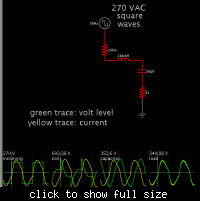
This is a simulation with scope traces.


The load calculates to be 53 ohms, since we want 1000 W at 230 VAC.

I wonder if I discovered something new? If the simulation is to be believed then this is an easy way to turn a square wave inverter into a sinewave inverter.

The square wave is converted to a sine wave. Notice the peak reaches a level matching the 1.414x peak of a sinewave. This is a genuine boosting action which occurs due to coil-and-cap resonance. The inverter value of 270 VAC square waves was arrived at by experimentation, in order to obtain 230 VAC sine.

The load receives 4.35 amps. (1000 W as specified.)

Components must be able to handle 6.4 A peak. The capacitor must be non-polarized. A bank of several capacitors ought to be used.

The combination of coil and cap values should yield 50 Hz resonance. Their individual values were chosen to yield the same impedance as the load.
 

Hi,

I would like to make an inverter having an input of 6V or less and probably get a fair amount of AC output. Could anyone suggest me a design, maybe using TL 494.
And does anyone know where I could probably purchase a Fuel Cell for good rate...
 

The first step would be to boost the voltage to run the TL494. TL494 has a minimum supply voltage of 7V. So, make sure you step up the low voltage to one suitable for running the TL494.
 

Status
Not open for further replies.

Similar threads

Part and Inventory Search

Welcome to EDABoard.com

Sponsor

Back
Top