venkatgandham
Junior Member level 2
Hello,
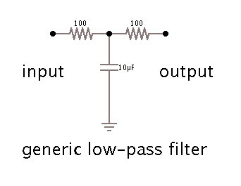
I am trying to find the criteria for the Low pass filter selection for Hall effect sensor.
From my understanding If I know the frequency of Hall effect sensor then I can find the R and c values and Design a Low pass filters.
But there are two obstacle mentioned below.
There are two types of circuits before the input of hall effect sensor can be applied to CPU or ECM.
Type 1
Type 2
Type 1:
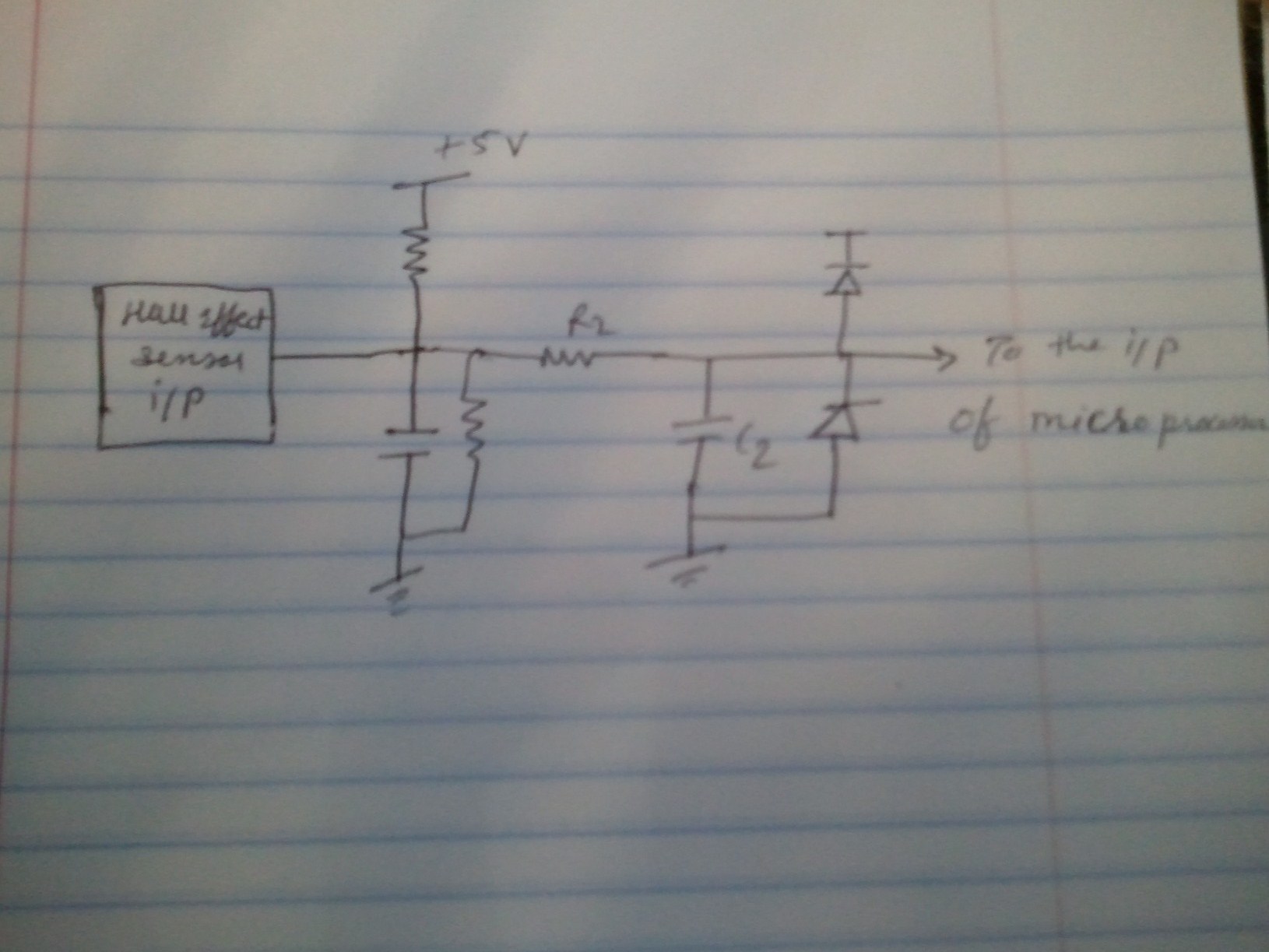
It has C1 (for ESD) and R1 resistors which is in parallel with C1 the output of both is given to Signal conditioning Circuit --> CPU or ECM.
Now I am confused where is the LPF filter in the type 1 circuit to restrict the high frequency inputs. My guess in signal conditioning circuit.
If that is true then how would I decide the vaules of C1 and R1. Why R1 is in parallel with C1. Which is missing in Type 2.
Type 2:-
It is open drain circuit, It has ESD Capcitor in parallel with the signal conditioning circuit. Now I would like to know why this Circuit doesn't have the R1 in Parallel with C1. Then comes the Signal conditioning circuit and output of the Signal conditioning Circuit is given to CPU or ECM.
Flow of Signals:-
Type 1: Hall Effect sensor o/p---> C1||R1 --> Signal Conditioning Circuit --> ECM or CPU.
Type 2: Hall Effect sensor o/p---> C1 --> Signal Conditioning Circuit --> ECM or CPU.
Please help me in identifying the criteria for designing the LPF for hall effect sensors. I appreciated your help
I am trying to find the criteria for the Low pass filter selection for Hall effect sensor.
From my understanding If I know the frequency of Hall effect sensor then I can find the R and c values and Design a Low pass filters.
But there are two obstacle mentioned below.
There are two types of circuits before the input of hall effect sensor can be applied to CPU or ECM.
Type 1
Type 2
Type 1:
It has C1 (for ESD) and R1 resistors which is in parallel with C1 the output of both is given to Signal conditioning Circuit --> CPU or ECM.
Now I am confused where is the LPF filter in the type 1 circuit to restrict the high frequency inputs. My guess in signal conditioning circuit.
If that is true then how would I decide the vaules of C1 and R1. Why R1 is in parallel with C1. Which is missing in Type 2.
Type 2:-
It is open drain circuit, It has ESD Capcitor in parallel with the signal conditioning circuit. Now I would like to know why this Circuit doesn't have the R1 in Parallel with C1. Then comes the Signal conditioning circuit and output of the Signal conditioning Circuit is given to CPU or ECM.
Flow of Signals:-
Type 1: Hall Effect sensor o/p---> C1||R1 --> Signal Conditioning Circuit --> ECM or CPU.
Type 2: Hall Effect sensor o/p---> C1 --> Signal Conditioning Circuit --> ECM or CPU.
Please help me in identifying the criteria for designing the LPF for hall effect sensors. I appreciated your help