Continue to Site

Welcome to EDAboard.com

Welcome to our site! EDAboard.com is an international Electronics Discussion Forum focused on EDA software, circuits, schematics, books, theory, papers, asic, pld, 8051, DSP, Network, RF, Analog Design, PCB, Service Manuals... and a whole lot more! To participate you need to register. Registration is free. Click here to register now.

DIY Moving Message Display

Status
Not open for further replies.
I have tried to download it and run the simulation software and it works. Maybe you need to install user device library that i attached. Or you need to browse for hex file location.
 
Last edited:

Mc code

hi your post is awesome... but were can i find the Micro controller code in the site plz tell me.... and thank Q for your project info.............................................................................
 

It doesn't help too much. The first thing to do is design driving hardware for LED matrix. Software is used to pump display data and control how data are displayed. Simple hardware need complicate software and vice vera.
 

Re: cd4514 led scroll circuits

Dear ME,

Thanks for sharing the Circuit.
what will be the solution for Common Anode (CA) display in this circuit? could you please suggest which IC could be used instead of ULN2003 & 74LS259 for CA display?

Regards,
Dileep
 

For my last post, i used Dot matrix that it's Rows are Common Anode and Columns are Common Cathode. Transistor PNP TIP42 as Row driver. I think, ULN2003A and 74HC595 is pretty good. But, if you're looking for another design, at professional board, i usually found SM16126 + 100 Ohm as column driver and SN74HC138 + APM4953 as row driver.
 

@Arch Zone, thanks for your answers. I am not looking for another design at professional board. I am doing this project for myself. some hobby fun at home :)


I was wiring the circuit in the "post #9" without considering CA display in my hand. I have 6, 7x5 matrix display brought earlier, and I thought that it was CC display. But it was CA display. So I removed the ULN2003

I have one more doubt here…
1) I connected 74HC259 directly to one display and I lit the first row. According to me, I felt its glowing fine. So, can I connect 6 7x5 together and drive each row with 74HC259? is it good?

2) In the above scenario, do I need to connect any transistor as row driver? could you please suggest a solution for 74HC259 and CA display?

Regards,
Dileep
 

I just look at post #9, and that is awesome design.
As that design add ULN2003, we told HC259 has no current output enough to drive all led in row. If you put 6 pcs, they will go dull, and the brightness can't be the same. When you enter character like : LLLLLL to the display, lowest row is dull because they need more current rather than the another rows.
To change with another common type of dot matrix, we need change ULN2003, NPN transistor array to PNP transistor array, UDN28xx, (but it's hard to find it in the market) or use 7 pcs of PNP Transistor.
 

Multi_lingual PIC18 MMD

zuisti's multi_lingual MMD, using my 'old' circuit. A working Proteus project is attached.
Also a screenshot (how are displayed for ex. the simplified Chinese chars).

For now only a rudimentary form, eg the rs232 control is not possible yet.

I know, there are some character-picture errors (such as the gaps between them), but I have used the proportional Windows Arial_MS_Unicode font without any changes. This font contains more than 38.000 characters ...

The system can display 64 fixed (known at compile time) messages, uses my newest and fastest routines to provide a nice horizontal left-to-right / right-to-left pixel-scrolling, a short message center-aligning, but only these. The source is almost full with assembly :) , it is not ready yet, so it is not public, sorry.

The messages are included in a unicode text file with a few control character added.

zuisti
 

Attachments

  • MultiLingual.jpg
    MultiLingual.jpg
    113.2 KB · Views: 229
  • Multilang_MMD_h0.zip
    37 KB · Views: 320
A zuisti's PIC16 MMD program, now in MikroC too

On request I made a simple Proteus project to show my newest MMD algorithm, using a PIC16F628A, 5x7 led matrices and one fixed message only. It is only a 'bare' program, to explain the algorithm, so it doesn't contain additional features.

I created the software also in two variants: in MikroC v5.60 and in Proton Basic v3.5.4.5. In both cases, only classical solutions were used, for max. portability. No inline asm (pure C and basic), and only the indexed array access is used (no pointer).

The version 01 programs are not optimized, to get a better clarity. They both are used in own Proteus project, the source-level debug can be used to follow the program operation. These initial versions are too slow (see below), so use them at 8 Mhz, to get a reasonable refresh rate.

In the following step by step will show how to make the program faster, in both language (see the additional C and BAS source files):

version 01:
scroll16c-01.c (1046 words, 46,8 Hz refresh rate at 4 MHz clock)
scroll16b-01.bas (967 words, 55.3 Hz)
- (about description see above)

version 02:
scroll16c-02.c (1031 words, 50.4 Hz)
- the same as 01 but array access by pointers
- only a bit shorter and faster but helps a lot to understand the next step
-- not converted to basic because no pointers in Proton

version 03:
scroll16c-03.c (1010 words, 60.4 Hz), the first significant improvement
scroll16b-03.bas (955 words, 70.0 Hz)
- the same as the C-only 02 but indirect array access by FSR and INDF (legal in Proton and also in MikroC)
- FSR is a char pointer (hardware char *), and INDF is the *FSR (hw too)
- only one FSR exists in a PIC16 (except the enhanced types) but three in PIC18

version 04:
scroll16c-04.c (990 words, 83.2 Hz), a new significant improvement
scroll16b-04.bas (944 words, 85.6 Hz)
- the same as 03 but the exact asm "rlf INDF" is also used (only twice),
- rather than to simulate the rotate with carry (as before). But ... it's not a pure C or basic now

version 0.5 in C:
scroll16c-05.c (976 words, 84.3 Hz)
- the same as 04 but the pattbuf array is merged into the linebuf array (faster rotating)
- not so useful in this simple case, shorter and faster a bit but more complex.

version 0.5 in basic (opt):
scroll16b-05-opt.bas (896 words, 120.5 Hz), a really significant improvement
- full hand optimalization with a lot of asm instructions, (á la zuisti :)
- the only once called subroutines are placed to their calling place (no gosub - return)

version 0.6 in basic:
scroll16b-06.bas (884 words, 124 Hz)
- the same as 05 bas but the pattbuf array is also merged into the linebuf array (like in C 05)
- not as useful in this simple case as I wrote above but later this solution can come in handy


Both project and the above additional sources are included in the attached ZIP file.

Might be useful to someone, I hope.

zuisti
 

Attachments

  • MMD16_c_b_opt.zip
    102.7 KB · Views: 411
  • MMD16.jpg
    MMD16.jpg
    157.4 KB · Views: 190
zuisti's PIC16 MMD ... build out the above circuit (some thought)

Can you do a vid matey ?
.. No, unfortunately I cannot nothing build already, because my vision is very bad (I'm 68 :sad:)

The above PIC16 circuit is a row-scanning system for 7x5 led matrices (7 Common Anode rows !). Only one row is switched on at a time, due the multiplexing. There are 11 matrices, 11*5=55 columns, this means that max. 55 leds lit at a time (in the 'worst' case).
If we assume that a static 20 mA LED current (usual value) give a proper brightness, then due the 1:7 multiplexing 140 mA (7*20) LED peak current should be, but this is too much. Fortunately, due the "persistence of vision", a 30-40 mA is also enough. We calculate with 35 mA/LED peak current, so the max. row-side current (for 55 leds) will be 55*0.035 = 1.925 A !!

Thus, the 7 pcs high-side row drivers (and also the power supply!) must be scaled for min. 2A peak current, so use here PNP power darlington transistors (like the TIP142) or P-channel power MOSFETs.

The HC595's max. output current is less than 10 mA/output if all 8 are on, so column-side drivers are also needed.

There are more possibilities:
- use 55 pcs (one for every columns) of small PNP emitter-follower transistors (not-inverting driver!)
- or use 55 pcs of small N-channel MOSFETs like the BS170 (inverting driver!)
- or use 8bit inverting or not-inverting buffer circuits (ULNxxxx)
- or (as I would do) use 7 pcs of tpic6b595 ic from TI, instead of the HC595s, without any driver. It gives much more current: 150 mA /output (or use the tpic6c595: 100 mA/output)

Be sure to use column-side current-limiting resistors (55 pieces!), to set the 35 mA max. LED current.
The resistance value can be defined with the Ohm's Law:
Consider the supply voltage value (5v),
- the LED voltage drop (red: normally 1.6V),
- the row-side driver voltage drop (1.3V at 2A is also possible),
- and the column-side driver (if any) voltage drop at 35 mA. For ex: 0.7v using PNP trans.
The so calculated value is usually around 15 to 60 Ohms !!
In this case: R = (5 - 1.6 - 1.3 - 0.7) / 0.035 = 40 Ohm

Software:

recommend the above Scroll16c-04.c (or -05.c) version (it is fast enough also on 4 MHz).

But if it is possible, use a small PIC18 but at least an enhanced PIC16 (and modify the source), not the PIC16F628A.
Why?
The normal (mid-range) PIC16 family doesn't contain separated PORTx alnd LATx registers, so an RMW (Read_Modify_Write) problem may be occur while handling the output pins. In this circuit it is often an RMW problem with the large capacitive loaded output pins (eg the STORE output pin drives a lot of HC595 inputs, and there are also long wires).Therefore, particularly at high MMD systems (many of HC595), personally I used always separate buffer circuits here, to reduce the capacitive load of the output pin(s).

The PIC16 RMW problem can be avoided also by software. A little program modifying is needed (the above examples are not included this), but for an experienced PIC programmer it is not a problem, I think so.
But by all means must be avoided the high capacitive load of the CLOCK and STORE output pins, else you might need to use some additional delay (nop) instructions.

zuisti
 
If you are ever in leicester UK and need a hand making things, I am *perfectness-in-a-box" when it comes to soldering small bits, I've just moved "down" to 0.05" legs "for fun", and I've a lot of real experience in LEDS, https://www.youtube.com/watch?v=17JAe7xlB9k will help explain a bit :) 
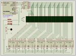
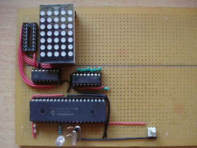
I am a *big fan* of the HTC1632c driven LED panels in this vid, PIC24 controlled SPI-LED-Matrix, lovely :) ... :)

Cool Mates,
NEAL of LightDiodeDesigns(member of the Commonwealth, European union, United-Earth-Design-Artists and human race)
 

hi to all..
please help me build my project led matrix moving display with ps2 keyboard input using pic877a and 74hc595 shift register..
by the way im using mikroc for the coding
heres my email
000000000000000@gmail.com

looking forward for your positive response to my post

MOD: NO PRIVATE SHARING..

ALL THE FILES ARE THERE TO DOWNLOAD. WHY DO YOU WANT TO SEND IT TO YOUR MAIL INSTEAD YOU CAN DOWNLOAD YOURSELF

NEXT TIME YOU WILL BE GETTING A WARNING
 
Last edited by a moderator:

Re: A zuisti's PIC16 MMD program, now in MikroC too

On request I made a simple Proteus project to show my newest MMD algorithm, using a PIC16F628A, 5x7 led matrices and one fixed message only. It is only a 'bare' program, to explain the algorithm, so it doesn't contain additional features.

I created the software also in two variants: in MikroC v5.60 and in Proton Basic v3.5.4.5. In both cases, only classical solutions were used, for max. portability. No inline asm (pure C and basic), and only the indexed array access is used (no pointer).

The version 01 programs are not optimized, to get a better clarity. They both are used in own Proteus project, the source-level debug can be used to follow the program operation. These initial versions are too slow (see below), so use them at 8 Mhz, to get a reasonable refresh rate.

In the following step by step will show how to make the program faster, in both language (see the additional C and BAS source files):

version 01:
scroll16c-01.c (1046 words, 46,8 Hz refresh rate at 4 MHz clock)
scroll16b-01.bas (967 words, 55.3 Hz)
- (about description see above)

version 02:
scroll16c-02.c (1031 words, 50.4 Hz)
- the same as 01 but array access by pointers
- only a bit shorter and faster but helps a lot to understand the next step
-- not converted to basic because no pointers in Proton

version 03:
scroll16c-03.c (1010 words, 60.4 Hz), the first significant improvement
scroll16b-03.bas (955 words, 70.0 Hz)
- the same as the C-only 02 but indirect array access by FSR and INDF (legal in Proton and also in MikroC)
- FSR is a char pointer (hardware char *), and INDF is the *FSR (hw too)
- only one FSR exists in a PIC16 (except the enhanced types) but three in PIC18

version 04:
scroll16c-04.c (990 words, 83.2 Hz), a new significant improvement
scroll16b-04.bas (944 words, 85.6 Hz)
- the same as 03 but the exact asm "rlf INDF" is also used (only twice),
- rather than to simulate the rotate with carry (as before). But ... it's not a pure C or basic now

version 0.5 in C:
scroll16c-05.c (976 words, 84.3 Hz)
- the same as 04 but the pattbuf array is merged into the linebuf array (faster rotating)
- not so useful in this simple case, shorter and faster a bit but more complex.

version 0.5 in basic (opt):
scroll16b-05-opt.bas (896 words, 120.5 Hz), a really significant improvement
- full hand optimalization with a lot of asm instructions, (á la zuisti :)
- the only once called subroutines are placed to their calling place (no gosub - return)

version 0.6 in basic:
scroll16b-06.bas (884 words, 124 Hz)
- the same as 05 bas but the pattbuf array is also merged into the linebuf array (like in C 05)
- not as useful in this simple case as I wrote above but later this solution can come in handy


Both project and the above additional sources are included in the attached ZIP file.

Might be useful to someone, I hope.

zuisti

please help me...

in your program in mikroc for led scrolling..

what if i will use an 8x8 led matrix display...what part of the program i will have to change?

thank you
 

Re: A zuisti's PIC16 MMD program, now in MikroC too

what if i will use an 8x8 led matrix display...what part of the program i will have to change?

Most importantly, the bitmap table should be changed to one which contains 8 pattern bytes for every chars.
The other (I think) is easy:
- Increased buffers: pattbuf[8] and linebuf[8 * 7]
- All "rowcnt ' loop counts now from 0 to 7 (or 7 to 0).

zuisti
 
Re: A zuisti's PIC16 MMD program, now in MikroC too

Most importantly, the bitmap table should be changed to one which contains 8 pattern bytes for every chars.
The other (I think) is easy:
- Increased buffers: pattbuf[8] and linebuf[8 * 7]
- All "rowcnt ' loop counts now from 0 to 7 (or 7 to 0).

zuisti


Hello, I am planning to add a ps/2 connection for keyboard input. I tried to connect it to the RB1 and RB2 but unfortunately PS/2_Config got error. is it possible to add ps/2 connection on your design?
 

Re: A zuisti's PIC16 MMD program, now in MikroC too

...is it possible to add ps/2 connection on your design?

Yes,
my above Proteus project is only for demonstrate the algorithm I'm using and supplemented with anything.

... and NO! (sorry):
I'm never using inbuilt libraries like the MikroC's PS2, I always prefer be using my own (so known for me) routines.
However:
- Seems this PS2 library is NOT an interrupt-driven solution so it cannot run in background and consumes a lot of time. In a such close timing system as the MMD, this is unacceptable, or at least requires a much higher PIC clock.

But, this is just my opinion ...

My proposal is to use RS232 communication (interrupt-driven, only RX), it is much easier to be implemented (also in HW).
Proteus has a Virtual Terminal for easy and simple rs232 simulation and in the reality, if your PC doesn't have serial port, use a USB-RS232 converter.

Good luck
zuisti
 

Status
Not open for further replies.

Part and Inventory Search

Welcome to EDABoard.com

Sponsor

Back
Top