Continue to Site

Welcome to EDAboard.com

Welcome to our site! EDAboard.com is an international Electronics Discussion Forum focused on EDA software, circuits, schematics, books, theory, papers, asic, pld, 8051, DSP, Network, RF, Analog Design, PCB, Service Manuals... and a whole lot more! To participate you need to register. Registration is free. Click here to register now.

Optocoupler swithcing 24vdc on and off.

Status
Not open for further replies.

louarnold

Member level 2
Joined
Jun 2, 2010
Messages
52
Helped
0
Reputation
0
Reaction score
0
Trophy points
1,286
Location
Canada
Activity points
1,754
I have a 24vdc battery supply. A manual switch now provides 22v to a signal wire (using only milliamps) I need to change this to have a micro-controller do the switching. It runs at 5v taking its power from the 24vdc via a 7805 regulator.

I have chosen an optocoupler to switch the 24 v on and and off to the signal wire. Will this work, or is there a better approach?
 

Yes, that is good if you have selected correct voltage optocoupler.
Also you can use little 5V signal relays. (search for "5V signal relays" on ebay)
 
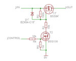
Personally I prefer this approach (If you have many MOSFETs handy, but not many optocouplers).
VIN is +24V, VOUT is your switched output, and CONTROL is connected to your microcontroller.
control.jpg
 

Re: Optocoupler switching 24vdc on and off.

Personally I prefer this approach (If you have many MOSFETs handy, but not many optocouplers).
VIN is +24V, VOUT is your switched output, and CONTROL is connected to your microcontroller.
View attachment 78650
Interesting idea. I still have to design components around the Opto. I'll see which uses less real-estate. (I'm not too good at electronics, so it will take awhile.)
 

Personally I prefer this approach (If you have many MOSFETs handy, but not many optocouplers).
VIN is +24V, VOUT is your switched output, and CONTROL is connected to your microcontroller.
View attachment 78650

This has a common ground for both input and output sides;
But opto-couplers and relays have completely isolated input and outputs from each other. (eg. input side is DC while output is AC)
http://www.pc-control.co.uk/relays.htm
http://www.bcae1.com/relays.htm

reladiod.gif

http://en.wikipedia.org/wiki/Opto-isolator
http://www.technogumbo.com/projects/Learning-to-Use-an-Optocoupler-or-OptoIsolator/

220px-Optoisolator_Pinout.svg.png
 

This has a common ground for both input and output sides;
But opto-couplers and relays have completely isolated input and outputs from each other.
I am aware of the function of optocouplers and relays.
If your microcontroller is being powered from the 24V supply via a 7805 (as mentioned in the original post), I think you'll find you already have a common ground.
 

I am aware of the function of optocouplers and relays.
If your microcontroller is being powered from the 24V supply via a 7805 (as mentioned in the original post), I think you'll find you already have a common ground.
Hmmm, yes, that's a good point. I had thought of using the mcu on a separate proto board at first with a separate power supply. The Opto would have been good then, but once finished, the subsystem gets powered from the battery, and so has the same ground.
 

I am aware of the function of optocouplers and relays.
If your microcontroller is being powered from the 24V supply via a 7805 (as mentioned in the original post), I think you'll find you already have a common ground.

Not meant only for you. Noted to distinguish both method for everyone. We see louarnold has got the advantage of everything posted here; and has made the decision based on it.
 

Status
Not open for further replies.

Part and Inventory Search

Welcome to EDABoard.com

Sponsor

Back
Top