Continue to Site

Welcome to EDAboard.com

Welcome to our site! EDAboard.com is an international Electronics Discussion Forum focused on EDA software, circuits, schematics, books, theory, papers, asic, pld, 8051, DSP, Network, RF, Analog Design, PCB, Service Manuals... and a whole lot more! To participate you need to register. Registration is free. Click here to register now.

Synchronized Communication Between 2 PIC16F877A

Status
Not open for further replies.

nooobboy4321

Junior Member level 1
Joined
May 22, 2012
Messages
18
Helped
0
Reputation
0
Reaction score
0
Trophy points
1,281
Activity points
1,447
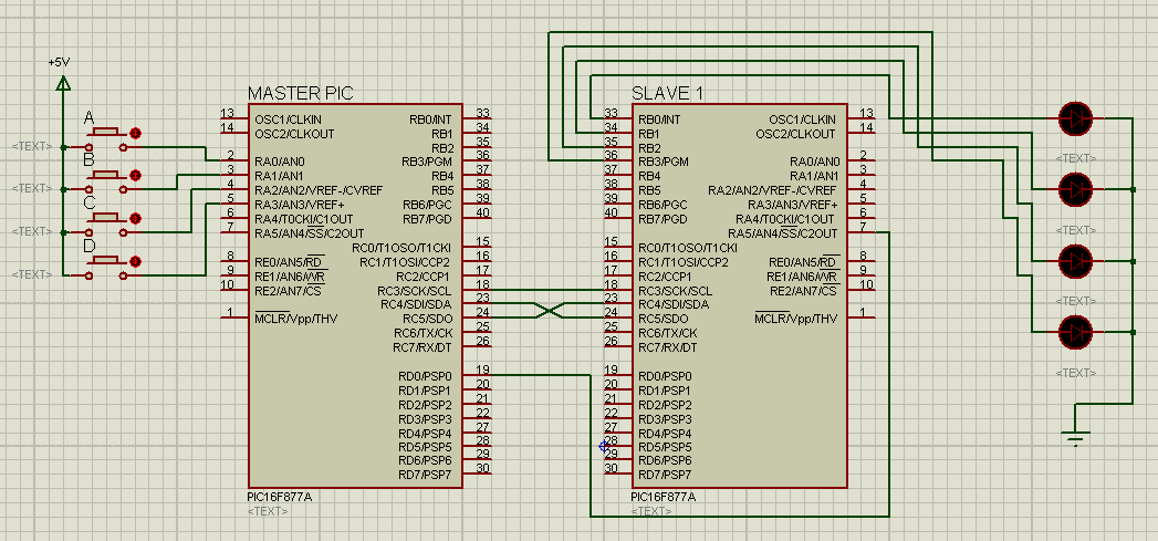
Hello Everyone, I have a question about Microcontrollers ability about sending and receiving data using I/O Ports only. My goal is to keep a synchronous sending and also receiving a data from MCU1 to MCU2. The logic is like this.................
---** LOGIC **---
*MCU1*
If RB0 is High
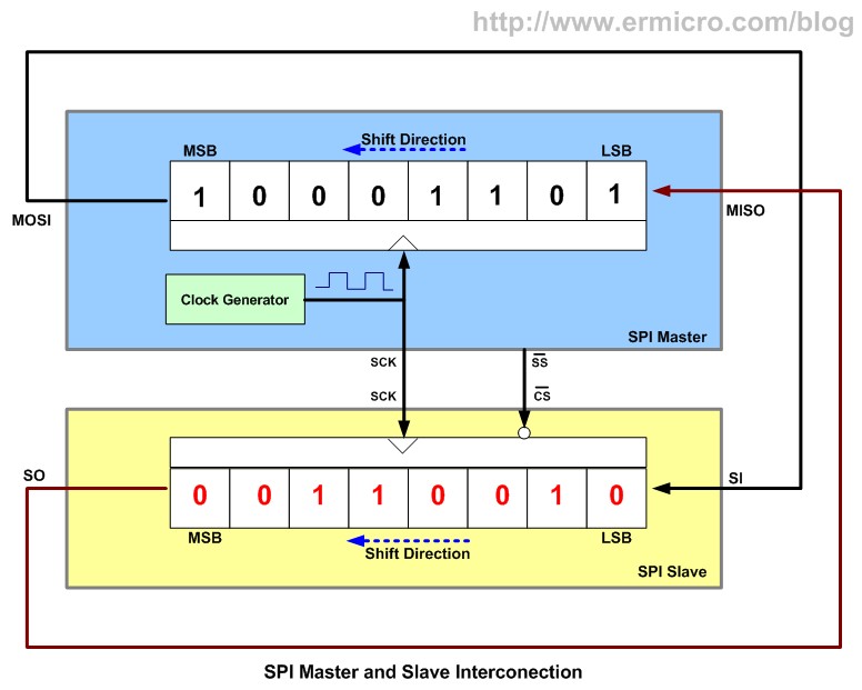
-- RD0 will output------------ 10011001,10011001,10011001,10011001,........
If RB0 is Low
-- RD0 will output------------ 01000010,01000010,01000010,01000010,........

*MCU2*
*The role of MCU2 is to check if RB0 receive a data in an array form and display the equivalent action of the array *
*For Example : A_ON[8] = {1,0,0,1,1,0,0,1} and A_OFF[8] = {0,1,0,0,0,0,1,0} *
If RB0 receives A_ON
-- UART will display output " A ON"
If RB0 receives A_OFF
-- UART will display output " A OFF "

---- I've tested it but I fail because of some delay. My question is, is there a way to fix this? By the way I'm using MikroC Pro and Proteus ISIS for simulations. If you have question about my problem, don't hesitate to ask me..... Thanks...
 

Hi,
What you are suggesting, manually sending out a series of pulses is called Bit Banging, basically software based serial communication.

Much simpler and safer if you use the chips inbuilt EUSART serial hardware, then you just tell it to output a whole byte at a time and the two chips will properly syncronize themselves

Do not connect the 2 chips EUSART pins RX to TX and TX to Rx directly togther, use a 1k resistor in series on each line, that helps protect the ports should you short them by connect them the wrong way around.
 
Hello, I'm not familiar about some special functions of SPI like...

SS
SSPBUF
SSPIF
BF

I read some forums about SPI and I find it very difficult to understand. HAHAHAHAHA...
I'm a newbie in MCU's ability.

Look at this thread.....
https://www.edaboard.com/threads/219637/

What's the role of this codes:

SSPSTAT.SMP =0;
SSPSTAT.CKE =0;
SSPCON.SSPEN = 1;
SSPCON.CKP = 1;
SSPCON.SSPM3 = 0;
SSPCON.SSPM2 = 0;
SSPCON.SSPM1 = 0;
SSPCON.SSPM0 = 0;
INTCON.GIE = 1;
SSPCON.WCOL=0;
SSPCON.SSPOV =0;


Please help me... :) Regards to all
 

avrspi_02.jpg
 
spi interface can be done with much ease ,as justin said in his picture. it just like handling a shift register. the blue one is so called the master chip (you have to assign one as master and the other as slave) the master determines the speed of data transfer by the clock i.e SCK. the data is shifted out serially ie MSB first to the slave (the yellow one). its can be implemented with ease and you must configure one as mater and the other slave. you also got to know which pins to be assigned as o/p s and which ones to be inputs. i can help you with the code.
code:
Code:
void spi_init()
{
    TRISC4 = 1;
    RC2 = 1;
    RC3 = 0;
    RC5 = 0;
    TRISC2 = TRISC3 = TRISC5 = 0;
    SSPCON = 0b00100010;
    SSPEN = 1;
    SMP = 1;
    CKE = 1;
    CKP = 0;
}
 
void spi_write(unsigned char kk)
{
    SSPBUF = kk;
    while (BF == 0);
}
 
void spi_read()
{
    SSPBUF = 0xff;
    while (BF == 0);
    readdata = SSPBUF;
}
PS : check the data sheet for more info. datasheets offer mighty help ;)
 
Hello Magnatron, I have a friend that shows me a sample of SPI communication using 1 Master and 1 Slave. So I'm sure that I learn a little bit about some setting of SPI into MCU but I know that it's not enough just to know the settings. Can you give me at least a simple code for my project using SPI Master to Slave V/V? The Logic is like I said on above. The Master is like a switch, if I toggle ON or if I toggle OFF RA0 , RB0 will send series of pulses. Let's say that If RA0 is Toggled ON, RB0 will output A_ON[] = { 1,0,1,1,0,0,1,1 };
Else If RA0 is toggled OFF, RB0 will output A_OFF[] = { 1,1,1,0,0,1,1,1 };
The Slave is only accepting inputs and checking the type of the data received from MASTER. Let's say that I set PORTD as Input, so If I get RB0 form Master and CONNECT it in RD0 of Slave, The Slave will check whether its A_ON or A_OFF by comparing the data receive from the MASTER and the array A_ON[] = { 1,0,1,1,0,0,1,1 }; and A_OFF[] = { 1,1,1,0,0,1,1,1 }; .....

I'm not thinking of using the EUSART of MCU because I have a plan for that.

Btw... This is my friend's code that he create just to show me an example of SPI through MCU. (hahaha Even if I really don't understand some codes that he puts on)

------------------------------MASTER-------------------------------
void main()
{
INTCON.GIE = 1;

ADCON1 = 7;
CMCON = 7;

TRISA = 0b00001111;
TRISC = 0b00010000;
TRISD = 0b00000000;

portd.f1 = 1;

SSPSTAT.SMP = 0;
SSPSTAT.CKE = 0;
SSPCON.SSPEN = 1;
SSPCON.CKP = 1;
SSPCON.SSPM3 = 0;
SSPCON.SSPM2 = 0;
SSPCON.SSPM1 = 0;
SSPCON.SSPM0 = 0;

while(1)
{
portd.f1 = 0;
SSPCON.WCOL = 0;
SPI1_Write(porta.f0 + porta.f1 * 2 + porta.f2 * 4 + porta.f3 * 8);
portd.f1 = 1;
}
}
------------------------------Slave-------------------------------
void main()
{
unsigned int buffer, gdata = 0;

TRISA = 0b00100000;
TRISC = 0b00011000;
TRISD = 0b00000000;
TRISB = 0b00000000;

ADCON1 = 7;
CMCON = 7;

INTCON.GIE = 1;

SSPSTAT.SMP = 0;
SSPSTAT.CKE = 0;
SSPCON.SSPEN = 1;
SSPCON.CKP = 1;
SSPCON.SSPM3 = 0;
SSPCON.SSPM2 = 1;
SSPCON.SSPM1 = 0;
SSPCON.SSPM0 = 0;

UART1_Init(9600);

while (1)
{
gdata = 2;

if (SSPSTAT.BF)
{
gdata = SSPBUF;
SSPCON.SSPOV = 0;
}
portb.f0 = gdata % 2;
gdata /= 2;
portb.f1 = gdata % 2;
gdata /= 2;
portb.f2 = gdata % 2;
gdata /= 2;
portb.f3 = gdata % 2;
gdata /= 2;
Delay_Ms(50);
}
}


Please help me, I need it badly. Regards to all :)

 
Last edited:

Status
Not open for further replies.

Similar threads

Part and Inventory Search

Welcome to EDABoard.com

Sponsor

Back
Top