Continue to Site

Welcome to EDAboard.com

Welcome to our site! EDAboard.com is an international Electronics Discussion Forum focused on EDA software, circuits, schematics, books, theory, papers, asic, pld, 8051, DSP, Network, RF, Analog Design, PCB, Service Manuals... and a whole lot more! To participate you need to register. Registration is free. Click here to register now.

Schmitt Trigger Oscillator

Status
Not open for further replies.
What in ***'s name are you trying to do with that poor op amp?

Things to try:
- Sane pin connections.
- Google image search for "Schmitt trigger oscillator".

What are you basing this circuit off of?
 
What in ***'s name are you trying to do with that poor op amp?

Things to try:
- Sane pin connections.
- Google image search for "Schmitt trigger oscillator".

What are you basing this circuit off of?

Trying to copy this sort of thing:

**broken link removed**

Fig6-OscCcts.gif


But what from what I have found so far it is not really clear to me how to connect the damn thing up.

Does a Schmitt trigger = Scmitt trigger oscillator? If so there are abundant detailed schematics for a Schmitt Trigger.
 

That symbol in the yellow image is not an op amp; it is a symbol for an inverting Schmitt trigger (the symbols can be inconsistent though).

The part number 40106 in the other image is **broken link removed**.

A Schmitt trigger is not the same as a Schmitt trigger oscillator; a Schmitt trigger oscillator is an oscillator built using a Schmitt trigger, as shown in the top circuit.

You can create a Schmitt trigger with an op amp comparator, then use that as the core of the oscillators. If multisim has a 40106 or other inverting Schmitt trigger part you can use that as well.

Check out https://en.wikipedia.org/wiki/Schmitt_trigger.

Dohh! :grin:

Will give it a go in multisim.

- - - Updated - - -

Here is a 741 Schmidtt Trigger but it aint doing what I understand it is supposed to be doing:


Based on the one in here: http://talkingelectronics.com/projects/OP-AMP/OP-AMP-2.html

- - - Updated - - -

The op amp oscillator example in that 'Circuit Simulator Applet' (http://www.falstad.com/circuit/) works well however.

But I can't figure out how to alter the duty cycle. Varying the resistor values and capacitor value only alters the frequency.
 

It ain't doing what it's supposed to do because a 741 won't work with a single 2V supply (hardly any op amp will). Try using at least a ±10V dual supply.

The 10kΩ feedback resistor will give a large value of hysteresis about equal to 1/4 the supply voltage.
 

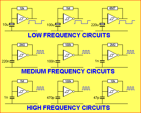
This doesn't work so what am I doing wrong here? I am getting -2kV or something similarly utterly rediculous.
Beware touching the computer screen. :)

It would be the first OP circuit that's working without connecting the OP output.

Post #5 is a step forward. Next increase the supply voltage to the legal 741 range and add the RC feedback between output and inverting input. You can keep the hysteresis settings for the time being, I think.
 
  • Like
Reactions: jasonc2

    jasonc2

    Points: 2
    Helpful Answer Positive Rating
But I can't figure out how to alter the duty cycle. Varying the resistor values and capacitor value only alters the frequency.
Changing the ratio between R8 and R9 should change the duty cycle.

Also, as Crutschow says, increase the supply voltage. The datasheet says minimum supply = 10V, but it would probably work with a 9V battery.
 

Another comment:
In post#5 I cannot see any negative feedback - and where is the capacitor?
 

Does a Schmitt trigger = Scmitt trigger oscillator?
Hi Boylesg
What do you mean by that ? an schmitt trigger not gate you have used ( 40106 ) is not an oscillator without feedback ! the yellow circuits that you have attached in post #3 are some simple relaxation oscillators based on RC networks !
What you want to do , ( i think ) is make an square wave oscillator with op amp ? is that correct ? if yes you can use a simple comparator ( such as LM311 ) and a simple RC network and another divider network .
( classical relaxation oscillator )
Best Wishes
Goldsmith
 
  • Like
Reactions: jasonc2

    jasonc2

    Points: 2
    Helpful Answer Positive Rating
crutschow said:
Try using at least a ±10V dual supply.

LM741 min supply voltage is 10Vpp, a ±5V dual supply will be fine.

godfreyl said:
Changing the ratio between R8 and R9 should change the duty cycle.

Changing resistors will not adjust the duty cycle of the oscillators from post #3.

boylesg said:
Here is a 741 Schmidtt Trigger but it aint doing what I understand it is supposed to be doing

You'll want a dual supply for the op amp for the Schmitt trigger. +/- 5V will work.

Start by building a Schmitt trigger. The inverting one on wikipedia with R1=R2=10k will work fine. Note the "Vin" and "Vout" labels on the schematic there. Those correspond to the input and output pins of the Schmitt trigger. If you draw a box around it and label Vin and Vout, it might help reduce confusion.

After building the trigger hook up as per the yellow diagram. A 10k resistor and a 10u cap should give you nice results.

This configuration creates a basic relaxation oscillator. In total you will have 1 op amp, 3 resistors, and 1 capacitor.

What is your intention with that function generator?

But I can't figure out how to alter the duty cycle. Varying the resistor values and capacitor value only alters the frequency.

In the oscillators you posted you cannot adjust the duty cycle by altering resistor or capacitor values. To adjust the duty cycle you need to make the Schmitt trigger thresholds asymmetrical.

For your oscillator you can do this by making the supply voltage to the op amp comparator asymmetrical, e.g. try +6V and -4V, or +5V and -10V.

Alternatively you can build an asymmetrical Schmitt trigger, e.g. **broken link removed**, which is also what you'd want to do if you want it to work with a single supply. This would generally be a better solution than asymmetrical supply voltages.

See https://pcbheaven.com/wikipages/The_Schmitt_Trigger/ for some clarity on the supply and symmetry; and there is an asymmetrical trigger component calculator linked down at the bottom of that page as well.

Note that constructing the inverting Schmitt trigger from wikipedia and then constructing an oscillator from it as per your yellow diagram creates the op amp relaxation oscillator circuit that you see in Falstad.
 
Last edited:
  • Like
Reactions: LvW

    LvW

    Points: 2
    Helpful Answer Positive Rating
Changing resistors will not adjust the duty cycle of the oscillators from post #3.
I was referring to the circuit in post 5.

To adjust the duty cycle you need to make the Schmitt trigger thresholds asymmetrical.
Exactly, and changing the ratio between R8 and R9 in the circuit in post 5 will do that.
 
  • Like
Reactions: jasonc2

    jasonc2

    Points: 2
    Helpful Answer Positive Rating
Exactly, and changing the ratio between R8 and R9 in the circuit in post 5 will do that.
Yes. For a symmetrical adjustment range (50% +/-x %), we would connect R9 to -Vcc instead of ground.

Jasonc2 was referring to the same option as "asymmetrical Schmitt trigger", but apparently didn't notice that it's already shown in post #5.
 
  • Like
Reactions: jasonc2

    jasonc2

    Points: 2
    Helpful Answer Positive Rating
I mixed up the circuits being referred to. Sorry about that.
 

LM741 min supply voltage is 10Vpp, a ±5V dual supply will be fine.


Changing resistors will not adjust the duty cycle of the oscillators from post #3.


You'll want a dual supply for the op amp for the Schmitt trigger. +/- 5V will work.

Start by building a Schmitt trigger. The inverting one on wikipedia with R1=R2=10k will work fine. Note the "Vin" and "Vout" labels on the schematic there. Those correspond to the input and output pins of the Schmitt trigger. If you draw a box around it and label Vin and Vout, it might help reduce confusion.

After building the trigger hook up as per the yellow diagram. A 10k resistor and a 10u cap should give you nice results.

This configuration creates a basic relaxation oscillator. In total you will have 1 op amp, 3 resistors, and 1 capacitor.

What is your intention with that function generator?


In the oscillators you posted you cannot adjust the duty cycle by altering resistor or capacitor values. To adjust the duty cycle you need to make the Schmitt trigger thresholds asymmetrical.

For your oscillator you can do this by making the supply voltage to the op amp comparator asymmetrical, e.g. try +6V and -4V, or +5V and -10V.

Alternatively you can build an asymmetrical Schmitt trigger, e.g. **broken link removed**, which is also what you'd want to do if you want it to work with a single supply. This would generally be a better solution than asymmetrical supply voltages.

See https://pcbheaven.com/wikipages/The_Schmitt_Trigger/ for some clarity on the supply and symmetry; and there is an asymmetrical trigger component calculator linked down at the bottom of that page as well.

Note that constructing the inverting Schmitt trigger from wikipedia and then constructing an oscillator from it as per your yellow diagram creates the op amp relaxation oscillator circuit that you see in Falstad.

My intention is to create a boost circuit to take +-12V to +-18V.

I have a number of opamps I have pulled off the circuit boards of discard electronic goods. So I was trying to figure out how to use them as a multivibrator in order to drive an inductor etc.
 

I am getting -2kV or something similarly utterly rediculous.
There's an important lesson there. Opamp spice models are often badly oversimplified which can result in completely unrealistic simulation results.

There's at least three symptoms:
  1. Output voltage is higher than supply voltage, as you found.
  2. The circuit works even though you forgot to connect the power supply to the opamp. Duh!
  3. The current from the opamp's output to the load magically comes from nowhere - there's no current flowing through it's power supply connections.


I just realized not long ago that this circuit contains a schmidtt trigger implemented with discrete transistors. It works really well for 18V under load but how would you modify it to get -18V?

I tried swapping the inductor, diode and capacitor down to the emitter of BD139 and reversing the polarity of the diode and capacitor but it doesn't work.

Suggestions?
 

I just realized not long ago that this circuit contains a schmidtt trigger implemented with discrete transistors. It works really well for 18V under load but how would you modify it to get -18V?

Just a quick idea: If and only if you don't require a common 0V reference with the computer, just hook your ATX gnd to the +12 input of this circuit (unmodified), and your ATX -12 to the ground of this circuit.

Then the +18 output of this circuit becomes your new ground, and the ground of this circuit is your -18V.

Your output -18 will be at the same potential as your ATX -12, and your output ground will be roughly ATX +6V.

Remember voltage is relative. Just keep in mind what's going on if you do that. E.g. do NOT connect your output ground back to the ATX ground or you'll just end up with a short circuit.

- - - Updated - - -

If you can do with -17V you can also simply use the atx +5 line as your "ground" and the atx -12 line becomes your -17. Again, though, only if you don't need a common ground reference point with the computer.
 

I am a little closer to the goal of -18V.

By replacing the battery with GND and -12Vee and reversing the polarity C10 and D1 I can get -12V going through the lamp. But why isn't the inductor working in this configuartion?
 

Why did you reverse the polarity of anything?

Replacing 0 and +12 with -12 and 0 doesn't change any relative polarities, it just shifts the 0 point and subtracts 12 from the numbers you previously saw.

Making that replacement and leaving everything else unchanged will change the outputs to -12 and +6 (relative to your input supply 0). That's still 18 volts.

If you want +18 use the lower output as output 0.

If you want -18 use the higher output as output 0.

Your meter shows +18. Swap the probes and there's your -18.

You haven't specified if you want your 0V output to be the same as your ATX 0V. If that's the case then yes, continue with your modifications. But if that's not the case, then you already have your -18.

Replace all this with a 3:4 voltage divider across your ATX -12 and +12, and there's another way to get + or - 18.
 

Status
Not open for further replies.

Similar threads

Part and Inventory Search

Welcome to EDABoard.com

Sponsor

Back
Top