Continue to Site

Welcome to EDAboard.com

Welcome to our site! EDAboard.com is an international Electronics Discussion Forum focused on EDA software, circuits, schematics, books, theory, papers, asic, pld, 8051, DSP, Network, RF, Analog Design, PCB, Service Manuals... and a whole lot more! To participate you need to register. Registration is free. Click here to register now.

[SOLVED] Audio Mixer Help: 3 channels to one

Status
Not open for further replies.

DFW Z33

Junior Member level 1
Joined
Jun 22, 2012
Messages
19
Helped
2
Reputation
4
Reaction score
2
Trophy points
1,283
Activity points
1,428
Hi guys, I am trying to make a simple audio mixer that will take 3 input channels (like my PC sound, iPod and Phone) and mix them into one output to a CMOY amplifier, and then to my headphones. I came up with this schematic, but Im sure it has several flaws which I was hoping you guys could help me find.

Also, I will be using the uA741 opamp, so I am really concerned that this schematic will cause a lot of noise in the signal.

Can anyone give me some tips on what I can do to improve on this design, or perhaps point me in another design direction?

Thanks!

Sorry for the crappy schematic, it's all I have to work with right now.
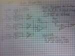
photo.JPG
 

It doesn't have particularly high gain so you could use 741s without noise becoming too much of a problem. Note that you need split supplies (positive and negative as well as ground) for this circuit to work. Performance will always be better if you use low noise amps of course.

Brian.
 
Ok, thanks for the input. So if I do the mixing with low or no gain, noise shouldnt be too bad? Then should I use a low noise op-amp for the CMOY high gain amplifier?

As far as the dual suppies, I plan on splitting a 12V DC source into a 6V+ and 6V- source by using a virtual ground via voltage divider. Would this work fine, or do I need a different supply?

Thanks again!
 

One minor suggestion: UA741 has null offset adjustment, if you have any problematic internal DC offset at any stage you may wish to add 10k trimpots (ref page 7 of http://www.ti.com/lit/ds/symlink/ua741.pdf) to correct. If you don't build them in perhaps leave space on your PCB in case you find you need them later.

You also may wish to throw 1u-5u caps in series at the inputs and outputs to remove signal DC offset (esp. at input where offset in one signal could get amplified in the output, and possibly clip signals to rails if the offset and gain are high enough). I would do this.

Check out this page it has some great clear basic examples and good explanations: http://www.all-electric.com/schematic/simp_mix.htm

BTW you don't need the buffers, just use large pots with large resistors in series for the inputs.

simp_mix.gif


- - - Updated - - -

As far as the dual suppies, I plan on splitting a 12V DC source into a 6V+ and 6V- source by using a virtual ground via voltage divider. Would this work fine, or do I need a different supply?

Also BTW this should be fine as long as you use an isolated 12VDC power supply otherwise you increase the risk of creating ground loops with other equipment (don't forget you'll be tying your signal grounds to 0V in your mixer).
 
Last edited:
mic-mixer-circuit.gif


The circuit is a basic 3 input mic mixer circuit with the popular opamp 741 ICs.
Two 741s are used here.U1, U2 are used as preamplifiers.
They produce a gain of around 40 dB to the individual input signals.
The U1 is wired as a summing amplifier to add the signals from three preamplifiers.
IC2 also gives a gain of around 5decibel to the final output signal.
Total gain of the system is around 45 dB.

http://www.free-circuit.com/2011/06/16/3-channel-microphone-mixer-circuit-with-ic741/


also see this with LM348 :

**broken link removed**

**broken link removed**
 
You will notice the common theme in all the previously posted designs is the virtual ground mixing point. The point about not needing to buffer the inputs is good but I would caution you that (using your original schematic) if R0, R1 or R2 are set to a low value, the input currents may be able to overcome the feedback current and the mixing point will no longer be a zero signal point. The comment on DC offsets is also valid, it would be wise to use coupling capacitors in-line with the inputs.

Noise is always present and normally unwelcome. What you should strive for is NOT to amplify the noise at the input of any op-amp, as your buffers are connected with unity gain, the noise they introduce will be low. The noise and DC characteristics of more modern amplifiers are vastly better than 741s.

Also beware of the supply voltage requirements of the 741, they don't work well at low supply voltages. Refer to the data sheet.

Brian.
 
Ok, thank you all for your help! A lot of great info here. The reason I had the input buffers was so that I didnt accidentally draw too much current from the source and damage the device, but I can see now that that is not necessary.
 

The reason I had the input buffers was so that I didnt accidentally draw too much current from the source and damage the device, but I can see now that that is not necessary.

Betwixt's point makes me realize I should clarify this: The key that will let you remove the input buffers is having a fixed resistor in series with the gain pot, which imposes a minimum input impedance when the gain pots are set low. Obviously, this affects your gain calculations. Keep input impedance requirements in mind when designing this.

That said if you have unused op amps (link) it doesn't hurt to use them as input buffers but do keep in mind that signals will be clipped to the supply voltage so if you do your gain adjustment after the buffers, you will have already lost large signals to clipping. So if you do use buffers, whether or not this is an issue is something you have to decide with your knowledge of what your input signals will be. (Which reminds me, if you're using multi-amp packages and have unused amps don't forget to tie them up -- see above link).

Ok, so this is not the first time I've heard someone caution me about the signal getting clipped due to supply rail voltage. Am I operating too close to the max signal voltage? I was under the impression that the audio signal coming from a standard headphone jack was +- 5V max. And then the +-6V supply gives the uA741 a 1V cushion to work with from supply voltage to signal voltage. Should I use a higher supply voltage?

Thanks again guys!
 

The problem isn't the supply voltage exactly, it's the maximum swing you can get at the output of the amplifier and you have to consider that as the output gets close to the positive or negative maxima (approaching clipping point) the distortion will increase significantly. Any DC at the input, whether from an external source or the internal offset of the amplifier will push the output voltage toward one of the rails and decrease the available range in that direction. To some extent you can optimize the DC offset by either using a nulling circuit or by selecting an op-amp with lower input offset voltage. 741s vary by manufacturer but typically have up to 6mV offset, if you have a voltage gain of x10 this can become 60mV at the output and it can propagate through the following stages.

A mixer of this type should really be used with input signals in the mV range, If your jack has +/- 5V on it, the amplifier output will almost certainly sit at it one or the other extremes of it's output range and the audio will be extremely distorted. If being fed from a headphone output, you should add a resistor across the input to simulate the load of the headphone itself, then couple the signal through a capacitor to eliminate any DC present on it, then use a potentiometer to set the level before feeding it into the mixer itself.

Brian.
 
Status
Not open for further replies.

Similar threads

Part and Inventory Search

Welcome to EDABoard.com

Sponsor

Back
Top